ESP01 programmer/breakout
prusaprinters
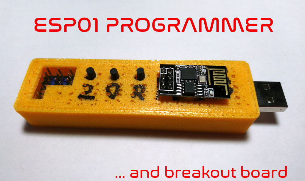
<p>This is an enclosure for an ESP01 programmer by AzDelivery (and similar, see picture). </p><p>Additionaly it is a breakout board for the pins and adds buttons for easy usage.</p><p>I decided to upload my ESP01 programmer, because it is so handy and neat … but unfortnatly I have no time to draw nice schematics. I added photos of the board form different views so you shoud be able to figure out how to solder. (ask if neccessary)<br>The PCB I uses is a 2x8cm board that come in a set you get from A… (the buttons are also available there in a set)</p><p>To connect the programmer to the PCB you have to sligthly(!) remove the solder of the 2x4 pin block with a solder sucker. Then put the programmer in the desired spot on the PCB and then you can solder your wires to it.</p><p>The resistors a for a voltage devider to support 5V on Rx serial pin. This is not ideal, but it worked. This part is definetly not neccessary, but sometimes handy…</p><p>Please excuse the bad print quality. This is an very old print from my first printer on his last days with bad filament. I didn't reprint this, because it does its job and yeah saving plastics is always a nice idea.</p><p> </p><p><strong>needed parts</strong></p><ul><li>ESP01 programmer (e.g. from AzDelivery, see photos)</li><li>PCB 20x80mm</li><li>3x 1k resistor (or 1x 1k and 1x2k)</li><li>3x buttons with minimum 6mm shaft</li><li>some wires</li></ul><p> </p><p><strong>print instructions</strong></p><ul><li>no special print instructions</li></ul><p> </p><p><strong>assembly</strong></p><ul><li>assemble the electronics</li><li>take the base part and slide board with USB plug first through the hole like seen in the picture</li><li>the pcb should fit snug tight. (if you want to pull it out use pliers)</li><li>place lid on top</li><li>use marker to mark function of buttons (R=reset 0=button gpio 2=button gpio2)</li></ul><p> </p><p><strong>usage</strong></p><ul><li>place ESP01 module onto the programmer. The board must face in USB plug direction, see photo</li><li>connect it to your computer</li><li>start your programming software (arduino IDE, esptool, …)</li><li>press button 0 and R at the same time</li><li>release R, but hold 0</li><li>when uploading begins you can relase the 0 button</li></ul><p> </p><p><strong>additional notes</strong></p><p>I'm interested in your feedback to improve my stuff! So give me likes, post makes, comment and rate the print to show others and me how well it goes.<br>If you post a make, let me know which filament you use.</p><p>If you want to support me by donating a coffee go to <a href="https://ko-fi.com/antimaterie">https://ko-fi.com/antimaterie</a> I would really happy about it. The money will be invested in all stuff regarding 3d printing to give more and better quality models.</p><p>In general my Prints are not for commercial use, but if you are a print farm owner and want to sell some of my stuff, please contact me.</p><p>Hope you enjoy my models.</p>
With this file you will be able to print ESP01 programmer/breakout with your 3D printer. Click on the button and save the file on your computer to work, edit or customize your design. You can also find more 3D designs for printers on ESP01 programmer/breakout.
