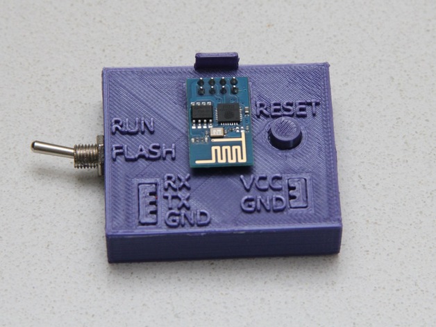
ESP 01 Programming Cradle
thingiverse
The ESP 01 (ESP 8266 based) is an extremely useful tiny WiFi-enabled board that shines when you upload new firmware into it. It's not exactly solderless-breadboard friendly, though - to switch between normal and flash modes, you have to connect and disconnect wires manually. I designed a little box that takes care of this hassle for you. One side connects to 3.3V power, the other to your PC using a serial adapter, and in the middle, you plug in your ESP 01 board. The design is based on my previous ESP 01 Connector project. This custom enclosure features a switch to select normal or flash mode, a reset button, and a small bump on top that ensures your ESP module can't be plugged in upside down. Parts I used: A toggle switch (I chose "New original 10pcs 3-Pin SPDT ON-ON Toggle Switch 6A 125VAC" from AliExpress) A push button, measuring 6x6x3mm The switch fits snugly into the round hole on one side of the enclosure, while the push button rests in a small cradle on the other side - see the picture with wiring instructions for more details. Note: Keep in mind that you might need to connect the switch differently depending on your specific model. In flash mode, the wires should be connected; in run mode, they should be disconnected. Also, make sure to match the TX/RX labels on the ESP 01 with those on the box - RX on the box goes to TX on your serial adapter, and vice versa. I created this design using SketchUp and then cleaned it up with Microsoft 3D Builder before slicing it with Cura. Finally, I printed it out on a Robo3D R1+ 3D printer.
With this file you will be able to print ESP 01 Programming Cradle with your 3D printer. Click on the button and save the file on your computer to work, edit or customize your design. You can also find more 3D designs for printers on ESP 01 Programming Cradle.
