EnderLoop
prusaprinters
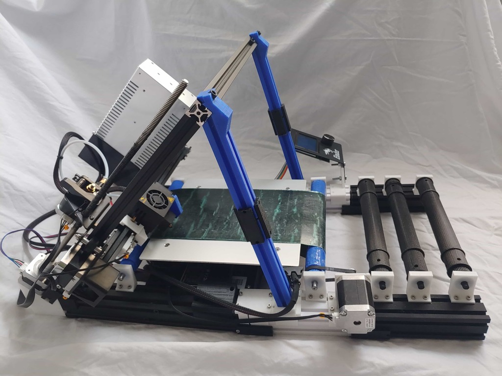
<p><strong>This has now been updated to the V2 version!</strong></p><p>I've cloned all the materials available here into a Github repo here: <a href="https://github.com/mcsgroi/EnderLoop">https://github.com/mcsgroi/EnderLoop</a></p><p><a href="https://www.youtube.com/watch?v=L337KpcwrPk&feature=youtu.be">Here</a>'s a great video with Adam at PowerBelt3D discussing the EnderLoop.</p><p>This supports around a 110x200xinfinity bed size.</p><p>I've attached a few pictures. Models in the printer pictures should mirror what is in the latest source files. Any differences should be minimal and are usually just that I'm running a slightly older version of the model to save on plastic waste. I've also included some test print pics to demonstrate the quality of what I'm getting off of the EnderLoop. In the pictures with two benchies, the black one is off of the belt printer whereas the white one is from a CR-6 SE as a comparison point.</p><h3>Note</h3><p>This is still a work in progress and you will most definitely find issues. Currently, I've identified a couple outstanding problems in my build:</p><ol><li>Adhesion. I'm just gonna say outright that this isn't terrible adhesion. It's just not as good as I like it. It really depends on the model height and surface area touching the belt. You can improve the adhesion slightly by "scuffing" the surface of the belt with sandpaper.</li></ol><p>Slight angle on some parts. I believe this has to do with esteps or cooling. Most of the remaining issues are fairly minor and should either be small model updates or software tweaks.</p><p>If you experience any issues, they are most likely a result of bed leveling. I learned this the hard way so certainly check this first. Bed leveling a belt printer is trickier than with a "normal" printer and can cause some strange issues (adhesion, angled prints, head collisions, etc.)</p><p>Lastly, I'll note, and this is less of an issue and more of a limitation, but this will print slower than a normal printer due to the lead screw being used as the "de facto Y axis".</p><h4>Parts</h4><h5>Printed Parts</h5><ul><li>2 - AngledSupport</li><li>2 - BedStandV2</li><li>2 - BeltSlide</li><li>1 - EndSensorHolder</li><li>2 - GantryBraceBottom</li><li>1 - GantryBraceHolderLeft</li><li>1 - GantryBraceHolderRight</li><li>2 - GantryBraceTop</li><li>1 - LcdHolder</li><li>1 - LeftBeltClip</li><li>1 - ModifiedMotorHolder</li><li>1 - PartCoolerVent</li><li>1 - RightBeltClip</li><li>2 - Updated45ZHolder</li><li>2 - UpdatedAxle or UpdatedAxleCrowned or UpdatedAxleSteelRod</li><li>4 - UpdatedYIdler</li><li>2 - YExtension</li><li>2 - YExtensionClamp</li></ul><p>11 - YExtensionSupport </p><p><strong>Optional</strong></p><p>1 - Scraper</p><p><strong>Extension rollers</strong></p><p>2 or 3 - UpdatedAxle</p><ul><li>4 or 6 - UpdatedYIdler</li><li>2 - Yextension</li></ul><p>8 - YExtensionSupport </p><h5>Purchased Parts</h5><p><strong>Belt</strong></p><p>Currently there are 3 options (there may be a 4th option when Creality's CR-30 belt is officially released):</p><ol><li>Buy a custom belt. There are some sites that are willing to sell a custom belt. I believe BuildTak is willing to custom make a belt, however the price is fairly steep (based on my research on the WhiteKnight printer).</li><li>DIY. I'll include a section here on how to make a belt yourself should you want to. Note that it's going to take some patience to get a clean surface and the performance (adhesion and ability of the roller to grip the belt) will be worse than option 3. The price point for this option is also going to be about the same as option 3.</li><li><a href="https://powerbelt3d.com/product/formula32-conveyor-belt-for-enderloop/">POWERBELT3D Belt</a>. I've reached out to Adam at PowerBelt and he was willing to list a custom belt that he has been working on that is specifically designed for the EnderLoop on his store. This is what I use right now and has pretty good characteristics. A couple of notes from the PowerBelt folks on this:<ul><li>For PLA, we recommend a bed temperature of 60-70C.</li><li>For PETG and TPU, they recommend a bed temperature of 70-80C. PETG tends to stick<i>very</i> well to the Polyester top layer, and might rip the material. They also recommend applying glue stick to the conveyor belt as a release agent to prevent this. If tearing still occurs, increasing the speed of outer contour that contacts the conveyor belt may help.</li></ul></li></ol><p>T Nuts - I would recommend buying an assortment pack like https://www.amazon.com/gp/product/B07FPLZXTF/ref=ppx\_yo\_dt\_b\_asin\_title\_o02\_s00?ie=UTF8&psc=1<br/>although you mainly need M3 sized parts (and the Ender 3 kit comes with a couple extra M4 T nuts in case you go that route).</p><ul><li>M3 washers to use as spacers for the hotend. You shouldn't need more than 4.</li><li>Assorted M3/M4 screws, mostly M3 8mm. I would recommend buying an assortment to slot in.<br/>Most of it is fairly flexible in what you use. Most holes in the parts I designed are for M3 screws, but you<br/>can enlarge the holes in the models if you go with another screw size.</li><li>2 M3 20mm screws and 2 M3 nuts for attaching the hot end lower on the print head mount plate.</li><li>4 M5 screws for attaching the gantry to the base. I would recommend they be 40-50 mm long since they will be holding the gantry, but the length is fairly flexible.</li></ul><p>2 M5 screws and 2 M5 nuts for attaching the lcd screen to the mount. I would recommend around 30 mm long, but, again, that's fairly flexible. </p><h5>Tools</h5><p>I've tried to make this install as "tool-less" as possible to make it accessible. That said, I've determined that in order to make this as functional as possible, there are a couple tools you'll need (or you can go to your local metal/machine shop to have done for you).</p><p>Drill with titanium bits (or another bit that can drill steel)</p><p>Dremel with a diamond coated cutting bit (or another bit that can cut steel) </p><h5>Optional:</h5><p>You may want to consider purchasing a few nylon washers to go above the springs, but below the heated bed. This will prevent damage to the heated bed from the metal spring. This is more of an Ender 3 design upgrade than an EnderLoop mod component, but I think it's worth mentioning, especially if you replace the default springs with stronger ones.</p><ul><li>I sadly managed to break endstops while I was tinkering with design and assembly. If you find yourself in a similar predicament,<br/>these work as replacements https://www.amazon.com/gp/product/B08G7Y5C63/ref=ppx\_yo\_dt\_b\_asin\_title\_o01\_s00?ie=UTF8&psc=1</li><li>I also unfortunately managed to fry my mainboard (specifically a driver) while I was tinkering and ended up replacing it with https://www.amazon.com/gp/product/B07TYFJ924/ref=ppx\_yo\_dt\_b\_asin\_title\_o01\_s00?ie=UTF8&psc=1. These boards are fantastic because the drivers on them are INCREDIBLY quiet. The loudest part on the printer after installing one of these becomes the fans.</li></ul><p>If your mainboard is V1.1.5, you will need either an Arduino or a USBTiny (https://www.amazon.com/gp/product/B07S9BX98K/ref=ppx\_yo\_dt\_b\_asin\_title\_o04\_s00?ie=UTF8&psc=1) </p><h5>DIY Belt Instructions</h5><p>In order to keep this lower cost, the backing is steel shim, which I taped into a belt using kapton tape.<br/>I then coated the hole belt in kapton tape. Your other options are PET tape or PEI sheets with an adhesive coating between the sheet and the steel shim.<br/>Steel shim link: <a href="https://www.mcmaster.com/steel-shim-stock/shim-stock-6/">https://www.mcmaster.com/steel-shim-stock/shim-stock-6/</a><br/>Instructions on sizing this are further down in the assembly information.</p><h4>Firmware</h4><p>You will note that there are a few combinations of mainboards/drivers that ender 3's can come with:</p><p><strong>Motherboards:</strong></p><p>V1.1.5</p><ul><li>V4.2.2</li></ul><p>V4.2.7 </p><p><strong>Drivers:</strong></p><p>HR4988</p><ul><li>A4988</li><li>TMC2208</li></ul><p>TMC2225 The precompiled firmware is meant for V4.2.7 and TMC2225 drivers (should also work with TMC2208 drivers). If you are using any other board/driver combination,<br/>you will need to edit the firmware I provided.<br/>Best I can tell, it seems that V1.1.5 comes with A4988, V4.2.7 comes with TMC2208 or TMC2225, and V4.2.2 can come with any<br/>of the drivers listed.<br/>V4.2.7 and V4.2.2 are simple enough to program. Simply place a compiled binary on a microsd card and insert into the printer.<br/>When you turn it on it will flash the printer. If it complains about mismatched EEPROM, just ignore it and update the<br/>EEPROM in the menu on the printer (lots of examples on the internet). If you have a V1.1.5, you will need to flash the firmware using<br/>and Arduino or a USBTiny (https://www.amazon.com/gp/product/B07S9BX98K/ref=ppx\_yo\_dt\_b\_asin\_title\_o04\_s00?ie=UTF8&psc=1).<br/>Not gonna go into to many details here as there's plenty of information on flashing the firmware available online.</p><p>Also worth mentioning is that the included firmware is a zip file. Thingiverse won't allow this as an upload type so I've simply added the .thing extension on the end. Just delete the extension when you want to extract the zip.</p><h4>Slicer</h4><p>You will need to install BlackBelt Cura to do belt printing. Once installed, find the install directory (C:\Program Files\BlackBelt Cura 3.6.0\resources on Windows)<br/>and copy/paste the Config folders I included here. This will prompt to overwrite a file, say yes. The config I included overwrites the BlackBelt default one.<br/>This should be fine since most people who can afford a BlackBelt probably aren't making this ;)</p><p>Also worth mentioning is that the included Cura file is a zip file. Thingiverse won't allow this as an upload type so I've simply added the .thing extension on the end. Just delete the extension when you want to extract the zip.</p><h4>Wiring</h4><p>As far as wiring goes, there are a few things to keep in mind. Look at the stepper motor cable wire order in the connectors (the prebuilt connectors that come with the printer).<br/>You'll note the middle two wires are inverted. Make sure you keep a close eye on whether a cable is supposed to have those wires<br/>inverted or not. The motor I purchased to drive the belt did not want those wires inverted, but all the Ender 3 motors do.<br/>One other thing to keep in mind is that all belt printers treat what we would normally consider the Y direction as Z. To<br/>accomodate this, you will need to plug the belt motor into the Y slot on the mainboard and the gantry motor into the Y slot on the mainboard.<br/>You will also need to plug the gantry end stop switch into the Y slot on the mainboard. You don't need a Z end stop switch (since there is no zero on a belt).<br/>Everything else should be wired the same.</p><h4>Print settings</h4><p>Everything was printed somewhere between a 20-30% infill except for the axles which were printed at 60% infill and the RightBeltClip which was printed at 80% infill.</p><p>You also may find the part tolerances to be too tight or too loose depending on how your printer is calibrated. You can either modify the models slightly to increase/decrease the size or use the horizontal expansion setting in Cura adjust the part prints.</p><h4>Assembly</h4><p>Assembly is fairly straight forward and most of it should make sense off of the pictures.<br/>To start, you will need to strip down a few parts that are on the Ender 3 already.<br/>Most of the parts you will be taking off are on the bed. You won't need the timing belt, motor, or aluminum extrusion directly under the bed. I've attached a picture to give you an idea of most of the parts you won't need.</p><p>You will need to keep the metal plate, screws, and tightening wheels right under the bed. This metal plate is what you will attach to the BedStand model and you should be able to attach it in the same way the wheels were originally attached (same nuts and bolts).<br/>Depending on how tight this model is to your aluminum extrusion, you can use T nuts and screws to secure the BedStand more tightly. As far as replacing the springs that come with the Ender 3, I would recommend experimenting with a few different spring tensions. I used two different varieties of spring since one side of my printer needed to be tightened down more than the other. I would also recommend putting a nylon washer on top of each spring (just under the heated bed) to prevent the spring from scraping the heated bed.</p><p>The gantry is mounted at a 45 degree angle. This is accomplished with the Updated45ZHolder and the AngledSupport files. Slide the AngledSupport on first to the aluminum extrusion base and then slide the gantry extrusion into it. Lastly, slide the ModifiedMotorHolder onto the end of the gantry extrusion and screw the Updated45ZHolder into the gantry extrusion (these screws should be the ones that come with the printer)<br/>and the base extrusion (these will be the longer M5 screws mentioned on the parts list). I only used two screws on the base extrusion since that seemed sufficiently sturdy.</p><p>The hot end needs to be lowered on the print head. This is where the drill with a titanium bit comes in. You will be drilling a hole to accommodate the M3 20mm screws that attaches the hot end to the print head plate. I've attached a picture of this, but basically the holes should be drilled as low as possible without reaching the point on the steel where it starts to curve. It should also be vertically aligned with the original screw holes. Once you've done this, you can mount the hot end using the M3 20mm screws and M3 nuts using 4 M3 washers (2 per screw) as spacers between the hot end and the steel print head plate. Note, these screws need to extend past the back of the steel print head plate exactly the right amount so you can install the washer. If it goes to far, the screws will grind on the aluminum extrusion when it slides left to right and you will run into problems.</p><p>Most likely the silicon sock that comes with the Ender 3 will have material that covers the brass nozzle on the hot end. You'll want to trim the silicon that covers the brass nozzle or it will hit the bed or your in progress print due to the 45 degree print angle.<br/>You'll also need to remove the print fan vent piece from the side of the print head and replace it with the PartCoolerVent.</p><p>The print head is mounted 90 degrees from how a standard Ender 3 is constructed. To handle this, you need to unscrew the wheels on the print head and mount the LeftBeltClip and RightBeltClip under those screws.<br/>The X axis timing belt slides into the slots on those two parts. Note that you'll want to install the timing belt on the LeftBeltClip before you resecure the wheels.<br/>Once that is in place, you should be able to install the print head on the aluminum extrusion and install the timing belt around the motor (like you normally would).<br/>Lastly, you'll need to install the EndSensorHolder on the side of the aluminum extrusion that the hot end is on. Slide it as far left as you can without the print head hitting the metal support that attaches to the extrusion. This is installed using a T nut. You will need to remove the limit switch on the X axis (it's at the end of this rod under a plastic cover where the timing belt runs). This limit switch can then be screwed onto the EndSensorHolder.</p><p>Next you will add the gantry support pieces. This will involve attaching the GantryBraceHolderLeft on the left aluminum extrusion on the base and the GantryBraceHolderRight on the right aluminum extrusion on the base. This provides a socket hole on top to install the GantryBraceBottom into each of them. On top of the GantryBraceBottom you will use 8 (4 on each) to attach the GantryBraceTop's. These will then screw in to the top of the gantry using the outermost screw hole (you'll need to remove the screw that was there already) and a couple extra M5 screws you should have lying around from stripping parts off of the Ender 3.</p><p>The next step is to extend the base. You will need to install two YExtension pieces at the front of the base (towards you) using two YExtensionClamp's and 4 YExtensionSupport's. I would recommend sliding the ModifiedMotorHolder onto the left YExtension before clamping the YExtension in place.<br/>These will be held in place using T nuts.<br/>You can then mount the ModifiedMotorHolder using T nuts on the left YExtension.</p><p>Note, for all of the roller instructions that follow, you will need to apply a lubricant to the rollers where they contact the idlers.<br/>You have 3 options for the rollers.</p><ol><li>UpdatedAxle - This is just a standard 3d printed roller.</li><li>UpdatedAxleCrowned - This is a 3d printed roller with crowning in the middle to keep the belt inline.</li></ol><p>UpdatedAxleSteelRod - This is a 3d printed roller that you insert a steel rod into the middle of for support. I would recommend option 3. Should you go this route, the only additional work you need to do is:</p><p>Cut the 3 ft steel rod into two, roughly 11in pieces (slightly longer is fine, but I wouldn't go shorter than that).</p><ol><li>Insert the steel rod pieces into two UpdatedAxleSteelRod prints. If it won't go through, I'd run a drill bit of a<i>slightly</i> larger diameter through the inside of the model to loosen the tolerance.</li><li>If the steel rod sticks a bit, that's fine. I used a hammer to finish the job. Having it tight is perfectly fine (and actually makes it a bit simpler to install). If it isn't tight, you'll want to apply an adhesive to keep it in place so it doesn't slide out. No matter which of the roller options you choose, you will install one of the rollers using two UpdatedYIdler's and T nuts at the back of the printer (just behind the bed).<br/>The next roller you'll be installing will be the one that the motor drives. The roller model itself won't be able to grip the belt as it stands. You need to coat this roller, including the teeth, in a thin coating of something "grippy". I found FlexSeal paint worked well.<br/>Then you will need to mount this roller using two UpdatedYIdler's and T nuts at the front of the printer (between the ModifiedMotorHolder and the bed).</li></ol><p>Category: 3D Printers</p>
With this file you will be able to print EnderLoop with your 3D printer. Click on the button and save the file on your computer to work, edit or customize your design. You can also find more 3D designs for printers on EnderLoop.