Ender 5 optical endstops
prusaprinters
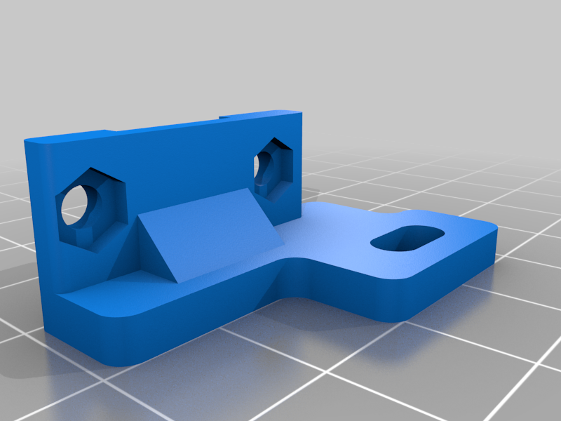
<h3> IMPORTANT NOTE feb 21st, 2021</h3> <p>This project is finished enough to be used, I will not abandon it, but I will also no longer give it care and attention, unless specifically asked for!</p> <p>Reason is, I have ordered a couple of 2209 drivers and will convert my ender 5 to sensorless homing.<br/> This is because the Y-axis is missing about 6mm due to frame-constraints and the X-axis only has about 5 mm total clearance. I think, using the hard boundaries as endstops with sensorless homing, I can dial in the exact build-platform positions using software and therefore optimise build surface.</p> <p>It might not be a smart plan, but at least I want to try :)</p> <p>So; if you need changes to this Thing, help in implementing, or any other thing at all, JUST ASK.</p> <h3> Update feb 21st, 2021</h3> <p>Created a new base (Y-axis part 1, v4) that uses an M3 T-nut.<br/> Reason is that a regular nut that can be moved back and forth for adjusting the distance, also rotates in the channel, so it is nearly impossible to affix the sensor tightly.<br/> The T-nuts rectangular-ish shape makes sure it will not rotate and therefore solves this problem.<br/> However; the channel needed for this T-nut is 6x5 mm and that means bridging large gaps and unavoidable overhangs.</p> <p>I AM rethinking the design, maybe drop some aesthetics in favour of printability, but for now, print upright with supports on the build plate.<br/> This will create a smooth channel for the T-nut to slide in, use an M3x8 bolt to affix the lot.</p> <p>When tuning the distance, keep an Allen key handy to trigger the sensor manually when the flag won't reach. (and with that prevent ruining your belts and motors.)</p> <h3> Update feb 17th, 2021</h3> <p>Switching back to "Work In Progress" because the "flag" is too large; the Y axis stops about 5mm to soon. Will tweak the length, and will try to make the endstop position configurable. Don't yet know how :P</p> <p>For now, just carefully measure, mark with a sharp knife and break away with pliers an amount of plastic of the "flag" so the Y-axis stops just short of the hard limit.</p> <h3> Update feb 1st, 2021</h3> <p>I am abandoning the idea of fitting this to a stock Creality board.<br/> I tested it with correct wiring, it did not work.<br/> M119 is showing "open" at all times instead of triggered<br/> I also tested the optical switches on an SKR 1.4 Turbo, and an MKS GenL, then they work just fine.</p> <p>So I ordered myself another SKR 1.4 Turbo with TMC 2208 in UART mode, and will use that in my Ender 5.</p> <h3>IN THEORY</h3> <p>the project below should work but I am unsure how to proceed to make it work on a Melzi (8-bit or 32-bit) board.</p> <p>Probably the reason is the Melzi board expects a short-to-ground as a trigger, whereas the sensors send a high (5v) signal instead. I did configure Marlin to accept a high signal</p> <h3>define ENDSTOPPULLDOWN_XMIN</h3> <h3>define ENDSTOPPULLDOWN_YMIN</h3> <p>but still did not work.</p> <h3> Update jan 9th, 2021</h3> <p>Revised the base mount and endstop mount (for y-axis)</p> <ul> <li>base is now higher, allowing space for an M3x14 bolt to go through and properly grab the nut, or, as I did (see picture) an M3x16 bolt with a nut screwed on first for better fastening.<br/> (well really, I didn't think it through and should have kept the base 2 mm lower so I could use an M3x12 bolt ... Probably will make a v3 ...)</li> <li>base is also redesigned to have more surface for the endstop mount to rest on, easier to mount, more stable in use.</li> <li>Hole for the M3 bolt is now a little wider so the bolt does not screw in but pushes through, also shifted a bit so the endstop mounts better.</li> <li>Endstop mount has smaller hole with less room for adjustment. This is to keep the part sturdier to prevent breaking it when mounting. Update jan 9th, 2021 + 3 minutes</li> </ul> <hr/> <ul> <li>Yeap, looks like I did make that v3. for use with an M3x12 bolt WORK IN PROGRESS!!!!</li> </ul> <hr/> <p>Optical endstops for Ender 5.</p> <p>This project covers</p> <ul> <li>X-Axis endstop</li> <li>Y-Axis endstop</li> <li>Electrical connections</li> <li>(additional) Hardware requirements<h3>Print Settings</h3> </li> </ul> <p><strong>Printer Brand:</strong></p> <p>Creality</p> <p><strong>Printer:</strong></p> <p>Ender 5</p> <p><strong>Rafts:</strong></p> <p>No</p> <p><strong>Supports:</strong></p> <p>No</p> <p><strong>Resolution:</strong></p> <p>0.2</p> <p><strong>Infill:</strong></p> <p>40%</p> <h3><strong>Filament:</strong> REAL PLA Orange X-Axis</h3> <p>The x-axis endstop mount has been designed, printed, tested and revised.<br/> It is designed to be mounted flush on the extrusion and then adjusted slightly to align the sensor to the hot-end mounting plate. The actual plate is used to interrupt the light in the sensor (something not possible with the y-axis endstop)</p> <p>You can re-use the original end-stop screw and t-nut, but you will need 2 M3x10 bolts and 2 M3 nuts.</p> <h3> Y-Axis</h3> <p>The Y-axis endstop is a 3 part item.<br/> 1 is a mount that fits the corner bracket with the stock hardware (m4x20 bolt with nylock nut)<br/> I added an M3 nut hole in the bottom so be sure to put it in, if needed; test the threading of the M3 bolt (with which you mount the endstop itself)</p> <p>2 is a the mount for the endstop, screwed in place.<br/> <strong>Warning</strong><br/> During test-fit I found that I was crushing the mount with the bolt. That's fine, won't come unscrewed, but you have only one go, I guess :P Make sure the switch lines up before tightening.</p> <p>3 is the part that interrupts the light beam. It is slid in place in the slot that holds the timing belt.</p> <p>for the Y-endstop you need;<br/> Original screw and nylock nut to mount part 1<br/> M3x10 (or x12) with nut to mount the endstop</p> <p><strong>v2 of y-axis mount fitted</strong></p> <h3> Electronics</h3> <h3>Reminder</h3> <p>I am not sure if the construction below will ever work. If anyone has insight in the electronics part, please feel free to contact me for corrections.</p> <p>The optical end-stops use 3 wires; VSG, 5v, signal and ground.<br/> Normally, however, the order is VGS, 5v, ground and signal, to shield the signal wire from the power wire.</p> <p>This means the cables need to be either purpose made, or reconfigured.<br/> As I have the tools to make my own cables, I will create the proper connections, but, the normal endstops of the Ender 5 are "powerless". There is no +5v on the connectors.</p> <p>For the 4.2.7 board I have in my Ender-5, I have designed the following;<br/> I will be soldering the sockets on a piece of PCB and wire them up as indicated.<br/> As the image indicates, I did think of the z-axis, but in my case I will not be populating those.<br/> Then I will create cables with 2-pin connectors to wire the adapter board to the mainboard.<br/> For the 4.2.7 board, a 3-pin cable is needed to wire the filament sensor connection. You don't have to use a filament sensor, it is just to get 5v.</p> <p>The optical sensors can then be connected to the bottom row. The sensors I bought have Dupont connectors on the board side, but the cables are way too short anyways, so I will be creating 3-wire cables with JST-XH connectors for those as well.</p> <p>So adding to the hardware list:</p> <ul> <li>4 (or 5) 3-pin JST-XH sockets</li> <li>2 (or 3) 2-pin JST-XH sockets</li> <li>2 (or 3) 2-wire JST-XH cables (short)</li> <li>1 3-wire JST-XH cable (short)</li> <li>2 (or 3) 3-wire JST-XH cables (long)</li> <li>a piece of PCB, at least 15 x 5 holes at 2.54mm pitch</li> <li><p>some wire to connect the sockets (to mimic PCB traces)<br/> Now, as you guessed, the "or something" numbers are in case you want to use an optical stop on the Z-axis as well. <strong>adapter board connections</strong></p> <p>Now for the 1.1.5 board, if you still use one of those, I have designed the following;<br/> As the 1.1.x boards do not have a filament sensor port, but do have an ISP header, I removed the Filament Sensor connectors and added a simple Dupont pin.<br/> You will need a jumper wire from the 5v pin on the ISP header, which is the one directly below the word ISP, the one closest to the USB port, at the edge of the board. If not yet clear, see image ;)</p> <p>So in this case, the hardware list includes:</p> </li> <li><p>1 dupont jumper wire (female both ends)</p> </li> <li>1 dupont header pin</li> <li>2 (or 2) 3-pin JST-XH sockets</li> <li>2 (or 3) 2-pin JST-XH sockets</li> <li>2 (or 3) 2-wire JST-XH cables (short)</li> <li>2 (or 3) 3-wire JST-XH cables (long)</li> <li>a piece of PCB, at least 15 x 5 holes at 2.54mm pitch</li> <li><p>some wire to connect the sockets (to mimic PCB traces)<br/> Once again, the "or something" numbers are in case you want to use an optical stop on the Z-axis as well. adapter soldered:</p> <p>All be amazed by my horrible soldering skills. I know how to do it, I just can't do it properly. It's all very small, I have big hands. Electrically it is all o.k., though. No short circuits between the V G and/or S wires.</p> <h3>Hardware</h3> <p>I used these end-stops:<br/> <a href="https://aliexpress.com/item/32959048821.html">https://aliexpress.com/item/32959048821.html</a></p> <p>I am not affiliated with AliExpress nor TwoTrees and there are LOADS of identical/rebranded switches out there.</p> <p>You will need either 2 or 3 of these :)</p> </li> </ul> <p><strong>My Ender-5 build so far</strong></p> <p><a href="/make:890134">https://www.thingiverse.com/make:890134</a></p> Category: 3D Printer Parts
With this file you will be able to print Ender 5 optical endstops with your 3D printer. Click on the button and save the file on your computer to work, edit or customize your design. You can also find more 3D designs for printers on Ender 5 optical endstops.