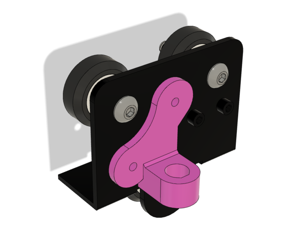
Ender 3 Trianglelab inductive sensor support
thingiverse
Simple support for Trianglelab's inductive ABL sensor (8mm diameter) https://www.aliexpress.com/item/33006152423.html I use this with the eB fan shroud https://www.thingiverse.com/thing:3419531 The values for NOZZLE_TO_PROBE_OFFSET are the following ```#define NOZZLE_TO_PROBE_OFFSET { -23.66, -2, 0 }``` --------- Trianglelab's ABL inductive sensor and SKR mini E3 (small guide) I recently got this small and affordable ABL sensor from Trianglelab store at aliexpress https://www.aliexpress.com/item/33006152423.html After a couple of days of tinkering, I finally got it sorted out, so I thought I'd share the steps. I'm using a SKR mini E3 board. Note that this sensor only works with metal beds (like spring steel + PEI). I tried on the original Creality surface and the original Creality glass bed, but the sensor LED just didn't turn on. Oh well. Steps: Print a support for the ABL sensor. You can use the one I designed, or print another one with an 8mm hole. https://www.thingiverse.com/thing:4111147 Make sure your bed is leveled against the Z endstop. The sensor will be installed along the existing Z endstop, so both will be working. The printer will home against the Z endstop as usual before probing. According to the sensor description, its head must be 1mm higher than the nozzle. So home your printer and turn it off. Keeping the Z at zero, put a 1mm spacer under the sensor and tighten it on the support. Slide the sensor cable inside the cable braid all the way to the mainboard. The provided cable should be long just enough. Connect the 3 sensor wires to the 3 'servo' pins of the board. You can use dupont connectors or solder a JST connector (I had one laying around from a LIPO balancer cable). The servo pins are GND, 5V, PA1 from top to bottom, so you need to connect blue, brown and black from top to bottom. Blue: ground, brown: 5V, black: signal. Refer to the SKR mini E3 diagram to be 100% sure. The wiring is done! Now on to the boring part, editing the firmware. Fire up VSCode and do the necessary changes. Some of those changes are taken from the TH3D EZABL config page. Marlin/src/pins/stm32/pins_BTT_SKR_MINI_E3_V1_2.h (swap servo pin with Z probe pin) ```#define SERVO0_PIN PC14``` ```#define Z_MIN_PROBE_PIN PA1``` Marlin/Configuration.h ```#define Z_MIN_PROBE_ENDSTOP_INVERTING true``` ```//#define Z_MIN_PROBE_USES_Z_MIN_ENDSTOP_PIN // comment this out``` ```#define Z_MIN_PROBE_PIN PA1``` ```#define FIX_MOUNTED_PROBE``` ```#define NOZZLE_TO_PROBE_OFFSET { -23.66, -2, 0 } // those are values for my setup``` ```#define Z_AFTER_PROBING 5``` ```#define Z_PROBE_LOW_POINT -3``` ```#define Z_PROBE_OFFSET_RANGE_MIN -5``` ```#define Z_PROBE_OFFSET_RANGE_MAX 5``` ```#define AUTO_BED_LEVELING_BILINEAR``` ```#define GRID_MAX_POINTS_X 4 // you can use 3 here if it takes too long``` Compile and flash the firmware. Add G29 after G28 in your start gcode and slice some bed leveling STL. I also added a 3mm retraction just before G29 because filament kept oozing while probing. Start the print, the nozzle will most likely be too high from the bed. Use Tune > Babystep Z and change it on the fly until the first layer looks good (I needed -0.500). Stop the print, go to Configuration > Probe Z Offset and set the value you got babystepping. Then store to EEPROM.
With this file you will be able to print Ender 3 Trianglelab inductive sensor support with your 3D printer. Click on the button and save the file on your computer to work, edit or customize your design. You can also find more 3D designs for printers on Ender 3 Trianglelab inductive sensor support.
