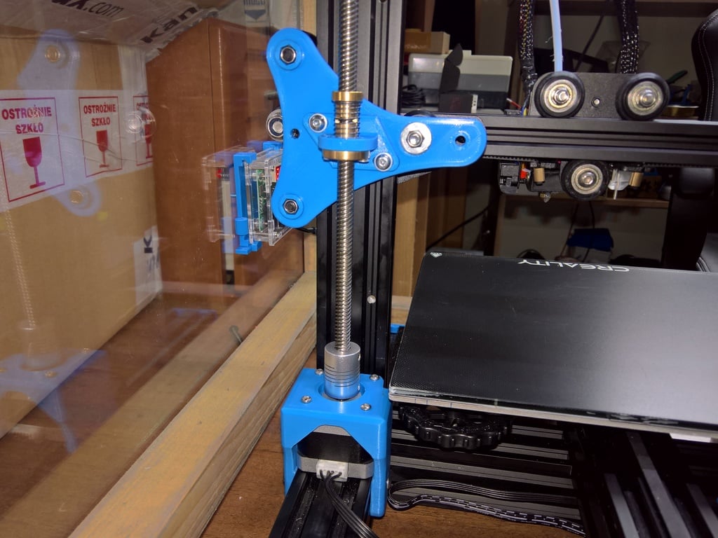
Ender 3 dual Z axis carriage , adjustable for antibacklash nut
thingiverse
Questions? Announcements. Support. https://www.facebook.com/groups/679001895990790 The Ender 3 is a fantastic machine, but it has its limitations. One of the main issues is that the X-axis gantry is supported only by one Z screw. Adding a second screw was a logical step to improve stability and precision. To take my printer to the next level, I wanted more precise movement from the whole Z assembly. That's why I decided to rebuild the way Z nut and screw are adjusted. This project requires patience and precision, so please keep in mind that it's not for beginners. My goal is to upgrade my Ender 3 with a dual Z axis system, using antibacklash nuts, dual Z motor, better motor mounts, bearing support for the Z axis, synchronizing belt for added precision, and fully adjustable axes for straight-line movement of the Z nut/screw. Right now, I'm at step one: designing and building another bracket to allow precise adjustment of the Z nut so that the Z screw is perfectly vertical. To help with this, I used a motor mount from OneEyedDesign (https://www.thingiverse.com/thing:2932344). I also added a bracket for the stock nut. Next up is step two: rebuilding the left side assembly without an extruder mount for direct drive setup (https://www.thingiverse.com/thing:4188950). Here's where I am so far: * Step 1: New bracket for second Z axis designed to allow precise adjustment of the Z nut, using motor mounts from OneEyedDesign. * Step 2: Rebuilding left side assembly without extruder mount for direct drive setup. * Step 3: Top adjustable bearing blocks for Z screws - completed (https://www.thingiverse.com/thing:4214242). * Step 4: Cable management adaptors - pending. Hardware and Assembly For the X-axis bracket, you'll need: - Leadscrew 8mm diameter, 2mm pitch, 8mm lead (stock screw) 370 mm length - Nut - designed for common spring-loaded antibacklash nut, but easily changeable - M5 x 40mm (or longer) - 3 pieces - Two spacers 8mm outer diameter, length 8mm, hole 5mm - Two or six M5 nuts - One small and one bigger spacer with 5mm hole - Two screws M4x12mm - Two M4 nuts Notes * Leadscrew: You can use a different lead, but you'll need to change both screws and nuts. My next step is changing the screw to 2mm lead for more precise movement. * Nut: The stock nut is terrible - very short with lots of wobbling and fast wearing. I recommend using antibacklash nuts or designing your own adjustable anti-backlash nut without a spring. * Motor: Use the same stepper motor as the main Z axis - 34mm length, 1.8deg stepper motor. I recommend using a board with dedicated drivers for dual Z like SKR1.3 or newer and disable stealthchop for precise movement.
With this file you will be able to print Ender 3 dual Z axis carriage , adjustable for antibacklash nut with your 3D printer. Click on the button and save the file on your computer to work, edit or customize your design. You can also find more 3D designs for printers on Ender 3 dual Z axis carriage , adjustable for antibacklash nut.
