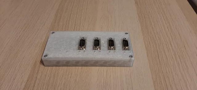
Encasing for the USB-COM232-PLUS4 circuit board
prusaprinters
More info on the PCB can be found here: https://ftdichip.com/products/usb-com232-plus4/The board is based on an FTDI chip. It is capable of converting 4 RS232 ports to USB. It has 4 DB9 (D-sub) connectors for the serial ports and a mini USB connector.These models include two different kinds of encasings for the USB-COM232-PLUS4 board.One of them can house one PCB while the other one can house up to two boards.What you will need:M3x6mm bolts (You might get away with slightly longer ones, for example M3x8mm).M3 washers.M3 heat set inserts. The parts are designed to accommodate the ones made by Ruthex: https://caribou3d.com/en/tools/919-19015-ruthex-heat-insert-nuts.html#/258-ruthexsize-m3The holes are around 4-4.2mm wide and 7mm deep.The parts you can see in the pictures were printed with PETG, but any material should do as long as you keep in mind the limitations of the material itself. In order to mount the PCB, you don't need to put threaded inserts in all the holes. The two columns in the middle can be left as is, it will still support the PCB. I personally didn't put a bolt here since there are vias on the PCB nearby, and I wasn't sure how possibly shorting those with the head of the screw would affect operation. Update: Two more models were added with the suffix “wider_holes”. Some serial connectors (for example the ones which can be assembled by hand, see the last picture) are wider than standard connectors and could not be plugged in while using the original encasing design. These models solve this issue, however the gap is bigger around the D-SUB sockets, revealing a bit of the PCB.
With this file you will be able to print Encasing for the USB-COM232-PLUS4 circuit board with your 3D printer. Click on the button and save the file on your computer to work, edit or customize your design. You can also find more 3D designs for printers on Encasing for the USB-COM232-PLUS4 circuit board.
