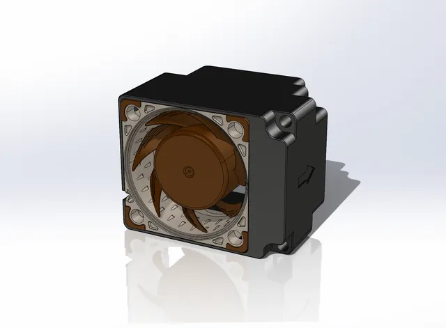
Elegoo Mars 3 Pro Noctua fan upgrade
prusaprinters
DISCLAIMER: I am not responsible for any damages to your printer nor any of the associated required materials. This modification requires some general electronics know-how and intermediate soldering skills. Please also note that this modification could impact your factory warranty, so owner discretion is advised. INSTALLATION INSTRUCTIONS:Materials: - 3D printed shroud - Noctua NF-A4x20 FLX 40mm fan - DC-DC buck converter (24V > 12V, approx. dim.: 22mm x 17mm) - Solder equipment (iron, flux, solder, etc.) - Flush-cut pliers/wire cutters - Hot glue gunPreparation: Depending on the model of DC-DC buck converter you will be using, it may be necessary to adjust the voltage output prior to installation. This can be achieved using an external power supply and alligator clips, or by soldering the original fan leads to the INPUT side as described in Electronics > Step 6. The desired voltage output should be measured at ~12VDC.Disassembly:Remove the (6) hex screws securing the rear access panel, then disconnect the (2) power wires from the LED driver module and set the panel aside. Disconnect the 2-pin fan connection (lower-right, middle connector) on the motherboard. Remove the (2) hex screws securing the bottom of the motherboard; it should be freely suspended. Carefully lay the Elegoo Mars 3 Pro on its side and remove the bottom (8) hex screws. Remove the base assembly. Locate the 45mm fan and remove the (2) Phillips screws. Electronics:Using a pair of wire cutters, cut the cable as close to the 45mm fan as possible to preserve its full length (with connector). This will be soldered to the new DC-DC buck converter. Using the same wire cutters, trim the cable on the Noctua NF-A4x20 fan, preserving at least 2-3 inches of length still attached to the fan (DO NOT REMOVE THE FULL LENGTH). Separate the three wires on the Noctua fan (red, black, yellow) then trim off the YELLOW wire. This wire is not needed. Strip approx. 2-3mm of jacket from each of the wire ends (4 total) then pre-tin the ends with solder (the use of flux is highly encouraged). Optional: pre-tin the solder pads on the DC-DC buck converter. Solder the original fan leads to the INPUT side of the buck converter, taking care to note which side is positive (red). Solder the Noctua fan leads to the OUTPUT side of the buck converter, again, taking care to note which is positive (red). Insert the Noctua fan into the printed fan shroud and press it firmly into place. Note the orientation of the wires through the shroud recess, and the direction of airflow in relation to the arrow on the shroud. Using the hot glue gun, carefully place a dollop onto the marked location of the shroud, then firmly press the buck converter into place (it is recommended to position the original fan leads towards the bottom for proper clearance). Reassembly:Position the new Noctua fan assembly onto the original 45mm fan standoffs, then secure it using the (2) original Phillips screws. Reposition the base assembly into the printer frame and secure it using the (8) original hex screws. Reposition the motherboard and secure it using the (2) original hex screws. Reconnect the fan connection onto the motherboard. Reconnect the (2) power wires for the LED driver module, then reposition the rear panel.Secure the rear panel using the (6) original hex screws. Enjoy the quiet operation!
With this file you will be able to print Elegoo Mars 3 Pro Noctua fan upgrade with your 3D printer. Click on the button and save the file on your computer to work, edit or customize your design. You can also find more 3D designs for printers on Elegoo Mars 3 Pro Noctua fan upgrade.
