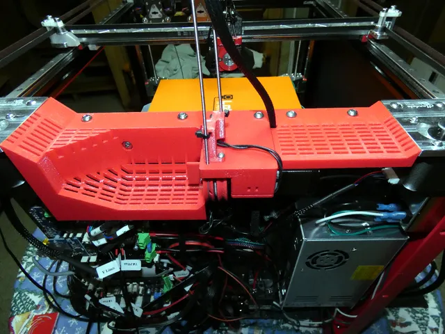
Electronics Enclosure for Jubilee
prusaprinters
I do not have a template/file for the HDPE back cover. HDPE was cut by hand with a router; I then tapped the ends of the Aluminum extrusions to hold the cover. Top PiecesTop pieces are anchored from the top with M5x14mm bolts. Top flat piece includes a version with and without wire notch.Sides and bottom:Sides and bottom subpanels can be anchored together with M3x10mm bolts and square nuts; Then anchored to the frame by removing the bolts holding the electronics back HDPE panel and replacing them with longer ones to go through my printed parts first (M5x10mm or M5x12mm).Bottom pieces include a panel with and without a keystone jack.Switches and PSU mount use M3 embedded hex nuts.PSU mount:PSU mount is designed for the astrodyne inlet, but I tried to make it easy to modify for others.I included panels to mount the power socket on the top or bottom, top option requires shorter steppers.Duet Side:I printed my duet side panel with a color change to clear and used a stick on RGB LED strip stuck to the back inside side of print facing front of machine.Included are blank panels for the duet side if you don't want to buttons, decorative vents, logo text or logo at all. Buttons where are also printed with a color change to clear for the LEDs.Switches:Switches use a PCB with tact switches and LEDs for back lighting.Switches are wired between ground “-”, and the “1-3"pins. Config should be set to enable pull up resistors, and inverted.RRF3.01 Example:M950 J0 C"!^duex.e6stop"; Input 0 connected to e6stop inverted with pullups M581 P0 T2 R0; Input 0 should run trigger2.g, anytimeEagle .brd can be found in a similar project of mine on Thingiverse (switchBoard-RailCoreX3-LEDs-15) or ordered through OSHPark. Requires:3x Tact Switch 6x6mm 5mm Through Hole SPST-NO6x 1206(3216) SMD LEDs3x 805 SMD Resistors I used 100 ohm, which is safe for 5V and the possibility if one LED in the pair was mis-soldered, it won't burn up the other.Connector 2.54mm 5 Pins Right Angle and corresponding plug and wire pigtails Openscad source files are included.side_v1_0.scad is used to render both sides and the bottom.I tried to make it easy to move and combine any of the options from the sides and the bottom, but there might be limitations/quirks.Most files received updates since printing (most very minor) so won't match the pictures and haven't been printed since.The logo svg's are modified from files on the Jubilee GitHub.Keystone jack is based on modified OpenSCAD code created by Marcus Wu shared on Github.
With this file you will be able to print Electronics Enclosure for Jubilee with your 3D printer. Click on the button and save the file on your computer to work, edit or customize your design. You can also find more 3D designs for printers on Electronics Enclosure for Jubilee.
