Dynamic Range MIDI Foot Pedal
prusaprinters
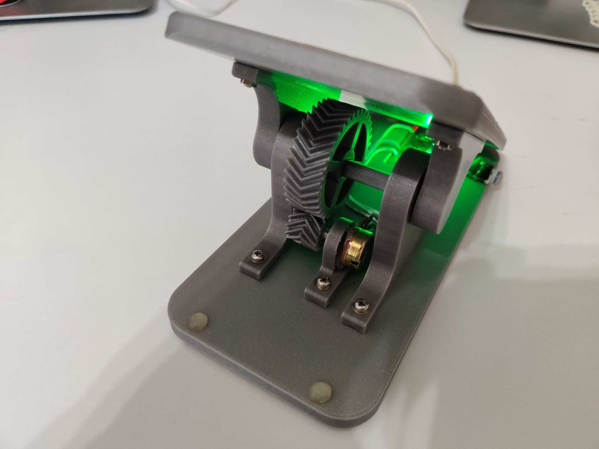
<h3>About</h3><p>I was looking to buy a MIDI pedal with a good range of motion and a fairly low price (mainly to control virtual instrument's expression/volume while my hands are on the keyboard, and my right leg is on a sustain pedal).</p><p>I didn't find what I was looking for, so I figured it's a good motivation to improve my CAD skills, and make my own.</p><p>My idea was to let the user choose the range they want, so... this pedal supports up to 80 degrees. While not expected to be fully used (I know I don't have that flexibility) different ranges work for different positioning of the pedal, and personal comfort.</p><figure class="image"><img src="https://media.printables.com/media/prints/272769/rich_content/b8e4a891-a56a-450d-8443-8a374887336f/animation.gif#%7B%22uuid%22%3A%2256a0a7eb-cb2c-491f-92df-786ecb7a8969%22%2C%22w%22%3A640%2C%22h%22%3A360%7D"></figure><h3>Behavior</h3><ul><li>By default, the full range is used.</li><li>A press on the blue side-button initiates range selection mode, which is enabled for 5 seconds. It's indicated by a blue light, and can be ended sooner, by an additional press on the button.</li><li>Range is chosen by moving the foot pedal back and forward, over the desired range.</li><li>After the range is set, it is saved to EEPROM (so it's not power depended).</li><li>Movements in the range are indicated by the green light (indicating MIDI commands are sent to the host) while movements outside of the range, are ignored.</li></ul><h3>Software</h3><p>Developed in C with the Arduino framework.</p><p>Code can be found <a href="https://github.com/nadavh/dynamic_range_midi_foot_pedal/blob/main/code/foot_pedal_arduino_mini.ino">here</a>.</p><h3>Hardware</h3><p>Mostly 3d printed (PLA) and split to avoid support material, and to be strong (in terms of printing orientation).</p><p>You can print the “part_groups” 01 and 02 (3mf or stl), or download the parts separately.</p><p>There is also "assembly.step", to help you customize the design.</p><p><strong>Additional parts:</strong></p><ul><li>Arduino Micro.</li><li>10 x 12mm M3 screws, washers and nuts.</li><li>2 x 608 (8 x 22 x 7mm) bearings.</li><li><a href="https://www.aliexpress.com/item/Free-shipping-50pcs-lot-size-12X12X7-3-push-button-Led-Tact-Switch-illuminated-switch/1428645429.html?spm=a2g0s.9042311.0.0.366c4c4dAUs27O">Micro switch with LED</a>.</li><li>B100K potentiometer (e.g. <a href="https://www.aliexpress.com/item/1005001421294754.html">https://www.aliexpress.com/item/1005001421294754.html</a>).</li><li>A glue of your choice (I've used hot-glue).</li><li>15 x Padding stickers (optional).</li></ul><h3>Assembly</h3><p><strong>Notes:</strong></p><ol><li>All screws will be connected from the top (with washers) to nuts at the bottom (of the relevant part).</li><li>The computer-generated images below don't show screws and wires (because I was too lazy to model them. Sorry about that).</li><li>I've used these externally available models:<ol><li><a href="https://grabcad.com/library/arduino-micro-1">Arduino Micro</a></li><li><a href="https://www.thingiverse.com/thing:4242664">Potentiometer</a></li></ol></li></ol><h4>Steps:</h4><ol><li>Solder 3 wires to the potentiometer (15cm each. You can cut them more precisely later).</li><li>Connect the potentiometer to the potentiometer_holder (Use glue): <img src="https://media.printables.com/media/prints/272769/rich_content/9492818d-5e8c-48c7-ae7c-5fedd1b20d09/s2_1.png#%7B%22uuid%22%3A%222fb553ea-1f50-437f-8119-4d67a9a698dd%22%2C%22w%22%3A480%2C%22h%22%3A270%7D"><img src="https://media.printables.com/media/prints/272769/rich_content/1abb5327-59ea-41bd-80df-40f0ed9aa16b/s2_2.png#%7B%22uuid%22%3A%220ff3fa5d-2185-434c-a690-21281f1dd5f4%22%2C%22w%22%3A480%2C%22h%22%3A270%7D"></li><li>Connect the potentiometer_gear to the potentiometer (make sure it's tightly coupled with the shaft): <img src="https://media.printables.com/media/prints/272769/rich_content/a030200d-17e0-40be-a622-b3b88fa9c180/s3.png#%7B%22uuid%22%3A%22de2209d0-f28e-43a1-a152-dc57a5559b47%22%2C%22w%22%3A480%2C%22h%22%3A270%7D"></li><li>Connect the potentiometer_holder to the base_plate, using 2 screws. Don't tighten the screws too much (allow the potentiometer_holder to slide on the rail, for later adjusments): <img src="https://media.printables.com/media/prints/272769/rich_content/28bd954f-34ab-49ab-9d27-835ed4d30384/s4.png#%7B%22uuid%22%3A%22e9a50751-13d5-499f-a2bc-68622b32f850%22%2C%22w%22%3A480%2C%22h%22%3A270%7D"></li><li>Connect the 2 bearings to the left and right bearing holders: <img src="https://media.printables.com/media/prints/272769/rich_content/11857a52-0647-49ca-ae01-8a331cb6326a/s5_1.png#%7B%22uuid%22%3A%22e100651c-7360-46fa-a941-c6b134c31490%22%2C%22w%22%3A480%2C%22h%22%3A270%7D"><img src="https://media.printables.com/media/prints/272769/rich_content/179fcbae-cc4f-4722-adb6-8d90684e8265/s5_2.png#%7B%22uuid%22%3A%22b3a28379-d468-4a77-8082-6847aac33484%22%2C%22w%22%3A480%2C%22h%22%3A270%7D"></li><li>Connect the right_bearing_holder to the base_plate with 2 screws: <img src="https://media.printables.com/media/prints/272769/rich_content/7297aa16-ab93-43a5-b05c-84cd7933f70e/s6.png#%7B%22uuid%22%3A%229769fb8b-dafa-402f-be86-02207fca7147%22%2C%22w%22%3A480%2C%22h%22%3A270%7D"></li><li>Connect the rod_gear to the rod. <img src="https://media.printables.com/media/prints/272769/rich_content/039c0b9b-ee39-42da-856e-62b0ca20d900/s7.png#%7B%22uuid%22%3A%2205fcd133-6812-4ae4-985b-45eaba6abb96%22%2C%22w%22%3A480%2C%22h%22%3A270%7D"></li><li>Push the rod through the bearing of the right_bearing_holder. Make sure it's oriented correctly, so that the rod_gear's teeth connect to potentiometer_gear's teeth when both gears are aligned: <img src="https://media.printables.com/media/prints/272769/rich_content/897db3bd-ebe5-40fa-a807-102e38761a11/s8.png#%7B%22uuid%22%3A%228ede4359-a67b-4d7a-abd6-d5ff6321a548%22%2C%22w%22%3A480%2C%22h%22%3A270%7D"></li><li>Connect the left_bearing_holder to the base_plate with 2 screws, pushing the other side of the rod into the left bearing: <img src="https://media.printables.com/media/prints/272769/rich_content/d6adbb27-4f97-4f81-8912-cd3580aca4fb/s9.png#%7B%22uuid%22%3A%22254ba09b-8aff-4dc8-90e0-eb5250915d2a%22%2C%22w%22%3A480%2C%22h%22%3A270%7D"></li><li>Make sure that rod_gear is aligned to the potentiometer_gear, and that a bit of the rod sticks from both sides of the bearing holders.</li><li>Connect both left and right rod connectors to the rod: <img src="https://media.printables.com/media/prints/272769/rich_content/d782273e-41ee-4485-abba-bc426a68e9a8/s11.png#%7B%22uuid%22%3A%22fa8a1839-5fc5-43a8-bbfa-548fe5043f88%22%2C%22w%22%3A480%2C%22h%22%3A270%7D"></li><li>Put the pedal on the left and right rod connectors, and connect the screws, <strong>without </strong>connecting the nuts: <img src="https://media.printables.com/media/prints/272769/rich_content/1ba2a4e1-e707-4e50-97c9-588dfd8ebe09/s12.png#%7B%22uuid%22%3A%2291c201eb-4506-42e2-886a-1c962543249e%22%2C%22w%22%3A480%2C%22h%22%3A270%7D"></li><li>Move the pedal back and forth, making sure both gears are in contact. Correct the angle of the potentiometer_gear, so that it moves together with the rod_gear and doesn't block it from moving the whole range of the pedal.</li><li>Disconnect the pedal from the rod connectors, and tighten the potentiometer_holder screws: <img src="https://media.printables.com/media/prints/272769/rich_content/d1d64fae-9a4e-4b09-b021-bf0e780a087e/s11.png#%7B%22uuid%22%3A%22eab9e065-c319-4064-ace5-be1babffba59%22%2C%22w%22%3A480%2C%22h%22%3A270%7D"></li><li>Solder potentiometer wires to Arduino (The picture below is from the finished assembly. In this step you only need to solder the marked wires):<ol><li>Potentiometer top wire -> Arduino GND</li><li>Potentiometer middle wire -> Arduino A0</li><li>Potentiometer bottom wire -> Arduino 5V <img src="https://media.printables.com/media/prints/272769/rich_content/848a048a-016d-44ac-b71d-b3b03e41f787/s15.png#%7B%22uuid%22%3A%225b221857-5d53-4542-b130-3e0caefc0322%22%2C%22w%22%3A477%2C%22h%22%3A263%7D"></li></ol></li><li>Solder micro_switch to Arduino (The picture below is from the finished assembly. In this step you only need to solder the marked wires):<ol><li>LED minus & one of the button pins -> Arduino GND</li><li>Other button pin -> Arduino pin 2</li><li>LED plus -> Arduino pin 3 <img src="https://media.printables.com/media/prints/272769/rich_content/bbe7670c-f9f2-4847-bdeb-1306f71e44d6/s16.png#%7B%22uuid%22%3A%22d0308a94-02d7-46f3-a5b7-569bc8e7c270%22%2C%22w%22%3A475%2C%22h%22%3A567%7D"></li></ol></li><li>Connect the micro_switch to the base_plate (use glue): <img src="https://media.printables.com/media/prints/272769/rich_content/3319e90e-add2-487c-97ef-188c07535794/s17.png#%7B%22uuid%22%3A%22a4ccc4e3-fed8-414a-94ce-e9de23d4e4b1%22%2C%22w%22%3A480%2C%22h%22%3A270%7D"></li><li>Connect the button_holder to the micro_switch and base_plate (use glue): <img src="https://media.printables.com/media/prints/272769/rich_content/493d4315-14ef-4c41-986e-5dcb8a20ad9e/s18.png#%7B%22uuid%22%3A%2267efebfe-c1fb-4422-a23d-e7fcb4b78f2b%22%2C%22w%22%3A480%2C%22h%22%3A270%7D"></li><li>Connect Arduino to the base_plate (use glue): <img src="https://media.printables.com/media/prints/272769/rich_content/c9d92e82-ca61-4fbe-94c9-d6cfea61bdb7/s19.png#%7B%22uuid%22%3A%22dea94417-9ab6-4594-8dc2-e6ef64517e6d%22%2C%22w%22%3A480%2C%22h%22%3A270%7D"></li><li>Reconnect the pedal to the rod connectors with screws and nuts.</li><li>Add rubber pads: <img src="https://media.printables.com/media/prints/272769/rich_content/76be81d6-c9fe-40c7-ae34-0cf91e8432a3/s21_a.png#%7B%22uuid%22%3A%222a5bda80-5334-48f0-b79d-d694fc10a2e6%22%2C%22w%22%3A480%2C%22h%22%3A270%7D"><img src="https://media.printables.com/media/prints/272769/rich_content/2dd640cb-79cf-4fdb-a00e-4d63c6838cfa/s21_b.png#%7B%22uuid%22%3A%225a0903be-358a-4a36-9cc8-aa797bdf8991%22%2C%22w%22%3A480%2C%22h%22%3A270%7D"></li><li>You can optionally add a pad to the button, to make it easier to press with your other leg.</li></ol><p>Have fun!</p>
With this file you will be able to print Dynamic Range MIDI Foot Pedal with your 3D printer. Click on the button and save the file on your computer to work, edit or customize your design. You can also find more 3D designs for printers on Dynamic Range MIDI Foot Pedal.