DSO150 Oscilloscope LiPo Battery Case
prusaprinters
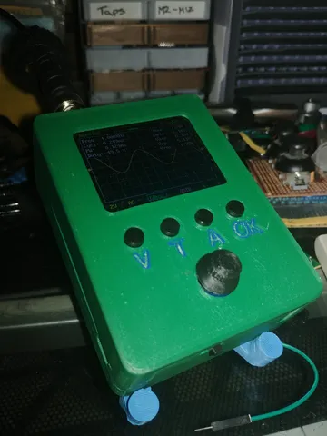
The DSO150 is a great small form factor oscilloscope marketed as being portable. This would be great except for one thing. Most versions are sold with no battery and require you to use an external 9V. In my experience your average 9V doesn't last very long and unless you buy one of those expensive rechargeable ones they're also a waste of materials.This one is designed to take a rechargeable LiPo battery pack. I originally used the old battery out of my LG G6 which was slowly losing its charge faster and faster but I later moved on to using a 5000mAh battery. I used a USB-C TP4056 to charge the battery and an MT3608 boost converter to step the 3.7V up to 9V. I used M2.5x30mm countersunk bolts and cut them short if necessary.BoMPartQuantityDSO150 Kit1TP4056 USB-C Charging Board1MT3608 Boost Convertor15000mAh Battery - 105575 (or any Lipo around 55x75x10mm or smaller)1M2.5x30mm Countersunk Bolts6Double sided sticky pads for mounting the battery, charging and boost convertor boards JST or Dupont Male Connector1JST or Dupont Female Connector1AssemblyThe circuit is relatively simple to hook up. In the end it should look something like this: If needed tap the 4 holes for connecting the 2 case halves together and the 2 holes that will mount the analog board with a M2.5x0.4 tap Using a multimeter set the voltage of the boost convertor to 9VSolder 2 wires to the 2 terminals marked ⊕ and ⊝ in the bottom left of the non display side of the board. There may be 2 header pins soldered to the board that will need removing.Mount the display to the case top using the small self tapping screws that would hold the board to the original casePush one of the dials onto the rotary encoder. The dial needs to have enough lateral movement such that the dial can be clicked.If needed extend or solder wires to the + and - terminals of the battery. They need to be long enough to comfortably reach the bridge that is part of the case bottom. Crimp one half of your chosen connector to the wires.Solder 2 wires to the B+ and B- terminals of the charging board. Crimp the other half of your chosen connector to these wires.Solder 2 very short wires between the OUT+ terminal of the charging board and the VIN+ of the boost convertor. Do the same for the OUT- terminal and the VIN- terminals.Solder the cables coming from the ⊕ and ⊝ terminals of the main board to the VOUT+ and VOUT- terminals of the boost convertor.Assuming the battery has some charge, connect the battery and turn the oscilloscop on, as long as the screen turns on and loads the firmware you are golden.Using some sticky pads stick the charging board and boost convertor to the bridge of the case bottom as well as the battery to the cavity of the case bottom. The charging board needs to be rigid enough that you can insert a USB-C cable into the charging board without the board coming loose.Mount the analog board using 2 M2.5x0.4 screws, these will most likely need to be cut down to 5-10mm in length.Connect the 2 halves of the case together using 4 M2.5x0.4 screws. Ensure the 2x10 headers of the analog and main board connect properly when doing this.
With this file you will be able to print DSO150 Oscilloscope LiPo Battery Case with your 3D printer. Click on the button and save the file on your computer to work, edit or customize your design. You can also find more 3D designs for printers on DSO150 Oscilloscope LiPo Battery Case.