DSO112A Module for the Modular Breadboard Kit V2
prusaprinters
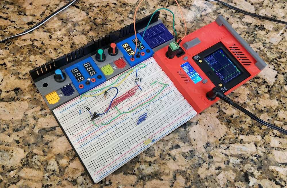
<p>This is a module that holds a DSO112a, with a DC-DC buck converter and a compartment to hold the DSO leads. It is designed to work with my "Breadboard Kit V2", which is designed to fit into a Stanley 014725R case. This thing is only the large (red) module in the pic, the rest of the parts are found in my "Breadboard Kit V2" linked below.</p> <p>There is a left and right side version of this module. This is due to the design of the breadboard kit which it is designed to work with. The large modules like this one, are left or right side orientated, but the smaller modules it works with (see the link below) are common to both left or right sided setups. For more info on the Breadboard kit, and the rest of the modules needed to complete one, check out the thing below:</p> <p><a href="https://www.thingiverse.com/thing:3416074">https://www.thingiverse.com/thing:3416074</a></p> <p>I would like to thank Mathgirl for sharing her (awesome) print in place hinge design, which I used on the DSO module door, you can check it out here:<br/> <a href="https://www.thingiverse.com/thing:436737">https://www.thingiverse.com/thing:436737</a></p> <p>MathGirl's Hinge Design (which the DSO112A module uses) is licensed under the Creative Commons - Attribution - Non-Commercial - Share Alike license. If you remix the DSO112A module or use the hinge design, please include the same attribution to Mathgirl for the hinge.</p> <p>I'd also like to note that I am not an electronics expert, just a hobbyist that is trying to get stuff organized. The steps and diagrams here show how I assembled the kit which I use, and there may be a better way so as always please use your own judgement. Please let me know if you see something that can be improved. As for the electronics, after the initial design I decided to add some fuses to protect the inputs for the DC-DC converters which I have included in the diagrams. I did not add any reverse protection or anything like that for any of the components, but please consider that if you see the need for it.</p> <p><strong>If making this, please understand the limits of the components being used, and make your own judgements on where, if, and how you feel additional protection such as fuses, PTC's or diodes are needed to make your project safe for how it will be used. If you see a problem let me know, thanks!</strong></p> <p><strong>Parts List</strong></p> <ul> <li><p>DSO112A oscilloscope (Ebay or <a href="https://www.amazon.com?linkCode=ll2&tag=thingiverse09-20&linkId=e4759bff1fa9a55a0f897d801ce2d765&language=en_US&ref_=as_li_ss_tl"> </a><a href="https://www.amazon.com?linkCode=ll2&tag=thingiverse09-20&linkId=e4759bff1fa9a55a0f897d801ce2d765&language=en_US&ref_=as_li_ss_tl"> Amazon</a>) (qty 1) https://www.amazon.com/KKmoon-Portable-Digital-Oscilloscope-Interface/dp/B01DKGBJQY</p> </li> <li><p>DC DC Buck converter Mine have an 5-23V input, and the seller stated they have a 3A max - but under 2A is recommended (much cheaper on Ebay) (qty 1) https://www.amazon.com/Converter-DROK-Adjustable-Stabilizer-Protective/dp/B01FQGFXS6/</p> </li> <li><p>Rocker Switch (qty 1) - rated for 6A 250V;10A 125V,10A 12V. I used the larger switches in this assortment: https://www.amazon.com/gp/product/B07D7NCLKF/</p> <p>These may also work:<br/> <a href="https://www.ebay.com/itm/5-x-Mini-Rectangle-Rocker-Switch-Black-Snap-in-SPDT-ON-OFF-3-Pin-12V-110V-220V/120875637487">https://www.ebay.com/itm/5-x-Mini-Rectangle-Rocker-Switch-Black-Snap-in-SPDT-ON-OFF-3-Pin-12V-110V-220V/120875637487</a></p> <p>There seem to be many of these toggles however so just make sure they fit the cutout which is 19mm x 12.8mm. The switches I am using have a dimension of 17mm x 12.8mm (measuring the body of the switch and not the larger face dimension, and not including the side clips).</p> </li> <li><p>DC 2.1x5mm panel connectors, these can be found cheaper on Ebay (qty 2) https://www.amazon.com/10Pack-Adapter-Connector-Dustproof-Lsgoodcare/dp/B078YP4CP6</p> </li> <li><p>Fuse to protect the DC-DC converter, I used a 2.5A fuse since that is what I have on hand (and my power supply only does 2A anyway). I recommend using a fuse to protect the electronics. <a href="https://www.arrow.com/en/products/025102.5mxl/littelfuse">https://www.arrow.com/en/products/025102.5mxl/littelfuse</a></p> </li> </ul> <p><strong>Hardware</strong></p> <ul> <li>M3x8 (qty 12)</li> <li>M3x16 (qty 4)</li> <li>M3x30 (qty 2)</li> <li>M3 nuts (regular, not locknuts) (qty 2)</li> <li>M3 4mm x 4.3mm brass inserts (qty 10, get some extras though)<br/> https://www.amazon.com/Uxcell-a16041800ux0833-Knurled-Threaded-Embedded/dp/B01IYWUUH8/</li> <li><p>1 spring from a retractable ball point pen, I used one like this. <strong>Tools and odds and ends:</strong></p> </li> <li><p>wire (I used mostly 22 gauge silicone insulated wire which doesn't tend to melt as easily when soldering)</p> </li> <li>soldering iron, solder, etc</li> <li>glue (I used clear Gorilla Glue but any glue that can be used with plastic would work)</li> <li>screwdriver and bits for the M3 and M2.5 screws</li> <li>heat shrink, electrical tape or liquid electrical tape</li> <li>several thin zip ties (only used on the larger modules for cable management). These need to be the thin kind since the opening in the cable management clips is only about 4mm wide.</li> <li><p>Electrical or Kapton tape for managing the wires. You can find instructions on assembly at the link below, but I have also tried to summarize them here (in the post-printing steps).</p> <p><a href="https://www.instructables.com/id/The-Modular-Breadboard-Kit-version-2/">https://www.instructables.com/id/The-Modular-Breadboard-Kit-version-2/</a></p> <h3>Print Settings</h3> </li> </ul> <p><strong>Notes:</strong></p> <p>The following parts have areas that need special attention since there are small pockets where supports could be a pain to deal with. They are:</p> <p>MBBKV2-D10-DSO-RIGHT-TOP -and- MBBKV2-D11A-DSO112A-LEFT-TOP</p> <p>I printed these so the top was flat to the build plate (rotated 180 degrees). There is a pocket where the door latch will catch, and another small enclosed pocket on the cable management tab, supports in these areas should be checked in the slicer before printing to make sure they will be removable (see the 5th pic showing where to check for supports). Using tree supports will avoid most problems. If you use Cura, the support blocker feature can also be used to insure there are no supports in an area.</p> <p>All the parts should be rotated and oriented for minimal supports. I found that the tree supports in Cura worked out well. If you use tree supports, I suggest that you also "enable support brim" and use at minimum a skirt with several lines, that will help with the adhesion of the tree supports to the build plate.</p> <p>STEP file is included if you want to make your own modules.</p> <p>I do not have S3D or other slicers, so if you have a problem, try slicing in Cura (which is free :D).</p> <h3> Post-Printing</h3> <p><strong>Putting it together - Step 1</strong></p> <p>To assemble, first install the M3 inserts according to the pics below. Make sure to fully seat the inserts, none should sit above the surface of the part, and the inserts for the 16mm screws should go in several mm before they bottom out. It can help to use a longer M3 screw as a tool to install them. It is best to melt the inserts in, but I don't have the tool for that so glued them in using Gorilla Glue.</p> <p><strong>This shows the location of the M3 inserts, and screws used. There are 2 regular M3 nuts that are inserted in the handle to mount it.</strong></p> <p><strong>Above shows the M3 inserts installed and the DSO module mounted to the base. I used M3x8mm screws to mount the DSO, but that requires the screws to self tap, a better way is to use double sided tape, velcro, hot glue or some other method that does not damage the DSO case.</strong></p> <p><strong>This is the latch cover, the M3 insert is shown on the top part of the latch. The pen spring is on the left.</strong></p> <p><strong>Putting it together - Step 2</strong></p> <p>Next, I installed the switches and DC connectors. Pre-wiring the connectors and switch may make it simpler. All the DC connectors can be secured with the backing nuts. The buttons for the DC converters need to be installed before installing the DC converters (otherwise they cannot be added later without removing the converters). I used a fuse on the converter to protect it (see the specs on the converter to determine fuse size). Heat shrink should be used to cover any exposed wire joints.</p> <p>It is necessary to keep the excess wires away from the bottom edge of the DC-DC converter which is a potential pinch point when the case is closed up (see the pic below).</p> <p>I provided a pic below showing how I wired mine up. It's a good idea to check that everything works once it is wired up.</p> <p><strong>This is how I wired up my DSO module. I used a fuse between the switch and the DC input jack (on the left side), to protect the DC converter.</strong></p> <p><strong>It is necessary to keep wires clear of the area around the bottom edge of the DC converters. There is a pinch point with the case when it is closed shown in the pic which is looking through the case from left to right.</strong></p> <p><strong>Putting it together - Step 3</strong></p> <p>The latch for the compartment that holds the DSO leads goes together using the A and B parts, a M3 insert (which should be installed and allowed to dry if glue was used), an M3x8mm screw and a spring from a cheap retractable ball point pen. See the pics below. The spring is put on the small "finger" that sticks out of the lower part of the latch, and the other open end of the spring will mount on the case side (where there is also a small "finger" that sticks out of the hole for the spring). Then the top of the latch is dropped on and the screw will secure everything from the bottom.</p> <p><strong>Putting it together - Step 4</strong></p> <p>Install 2 M3 nuts (not locknuts) in the handle as shown in the pic. If you have difficulty, make sure all the support material has been removed from the handles first, also, the nuts go in at an angle. The M3x30mm screws will be used to mount the handle during final assembly.</p> <p><strong>Putting it together - Step 5</strong></p> <p>Last step is to close up the case and use the screws noted in the first pic below. However keep in mind that this module works with the rest of the parts in the Breadboard Kit V2 (<a href="https://www.thingiverse.com/thing:3416074">https://www.thingiverse.com/thing:3416074</a>) - so the screws shown below are specified with the assumption that it will be connected to the other parts of the kit (the breadboard base and the small breadboard modules on the side. If this is being used without the rest of the modules from the kit, use shorter screws as needed.</p> <p><strong>Take care not to pinch the wires in the case, or under the DC-DC converter or switch (see the second pic below).</strong></p> <p>I used Kapton tape to help manage the wires and keep them out of the way of the mounting holes and other obstructions when closing the case. There is also a point below the DC input connector where a thin zip tie can be used to help with cable management.</p> <p><strong>It is necessary to keep wires clear of the area around the bottom edge of the DC converters. There is a pinch point with the case when it is closed shown in the pic which is looking through the case from left to right.</strong></p> <p><strong>Kapton tape was used to keep wires managed, and away from any of the pinch points, before the case was closed up.</strong></p> Category: Electronics
With this file you will be able to print DSO112A Module for the Modular Breadboard Kit V2 with your 3D printer. Click on the button and save the file on your computer to work, edit or customize your design. You can also find more 3D designs for printers on DSO112A Module for the Modular Breadboard Kit V2.