Drogerdy - Raspberry Pi Controlled Tank Bot
myminifactory
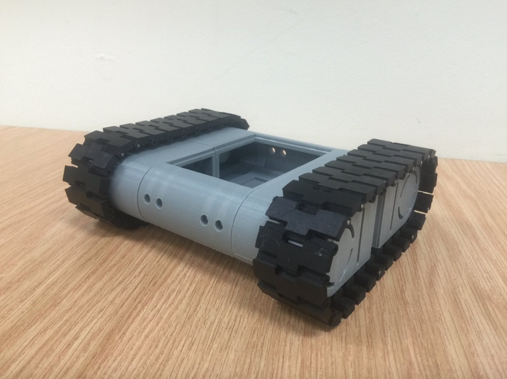
The second prototype out of the jRobot project makes use of a number of simple parts to do a whole lot.\r\nI've updated it to make it more versatile, and the tracks are now a little more grippy as well!\r\nhttps://www.youtube.com/watch?v=MJIx0cyOL3s&feature=youtu.be\r\n\r\nThe jRobot project allows my students to dock their Raspberry Pi with any of the robots, plug everything in, and program away.\r\nThe sample build shown makes use of the MCP3008 ADC to allow the RPi to access a range of analogue sensors including the Sharp 2Y0A02 Infrared distance sensor.\r\nIt has the same pin-based docking system as the Apogee Robot (https://www.myminifactory.com/object/apogee-raspberry-pi-robot-16326)\r\n\r\nInstructions\r\nYou'll need 26 tracks per side. The tracks are joined by 35mm long 2mm stainless steel pins, which hold the RPi in place.\r\nEach track assembly will need: 2 x Cogs; 2 x Inner Cog Brackets; 2 x Outer Cog Brackets; and 1 x Track Mid Frame (I'm still testing the improved inner frame).\r\nThe two track assemblies are then joined by 2 x body parts. The motors must be installed before the body parts are glued together.\r\nI use 5 minute epoxy to glue everything together, and a tip of each stainless steel rod is helpful to stop the tracks from falling apart.\r\nThe motors fit directly onto the cogs, which are no-name yellow geared ones that you can find on eBay (http://www.ebay.com.au/itm/1pcs-Anti-interference-f-Robot-Smart-Car-Chassis-DIY-DC3V-6V-DC-Geared-Motor-TT-/291314517942?pt=AU_B_I_Electrical_Test_Equipment&hash=item43d3b2c7b6)\r\nThe motor controller in the same bot is an L298N board, which fits perfectly in the bottom of the tank body. (http://www.ebay.com.au/itm/1pcs-Anti-interference-f-Robot-Smart-Car-Chassis-DIY-DC3V-6V-DC-Geared-Motor-TT-/291314517942?pt=AU_B_I_Electrical_Test_Equipment&hash=item43d3b2c7b6)\r\nThere are 4 x 5mm holes for LEDs and a square hole that allows for a sensor bracket and cable access.\r\nI use a Step Down Buck power regulator with a USB output to power the Pi, while the motors run straight off the battery. This means the Pi will restart when the batteries run low. I use 2 x 9V rechargables (500mAh each), which allow for a good 30+ minutes of run time.\r\nI use an Adafruit perma proto quarter size breadboard for the breakout board and header pins so that my students can use jumper cables to wire it up.\r\nThe sensors are up to you, but I'm using two Sharp infrared sensors on this one, which run through an MCP3008 ADC and interface with the RPi via the SPI bus. I also have a light-sensitive resistor on it and plan to add a sensor at the rear and one facing down to prevent the robot from driving off cliffs.\r\nI've got plans to be able to extend the length of the track assembly by adding a third cog, but I need to overcome some derailing issues.\r\n\r\nBelieve it or not, this one was printed on an Up! Mini because I didn't have access to my school's larger printer over the summer break.
With this file you will be able to print Drogerdy - Raspberry Pi Controlled Tank Bot with your 3D printer. Click on the button and save the file on your computer to work, edit or customize your design. You can also find more 3D designs for printers on Drogerdy - Raspberry Pi Controlled Tank Bot.
