DIY fine dust quad cyclone (stage 2) for ~ 80€
prusaprinters
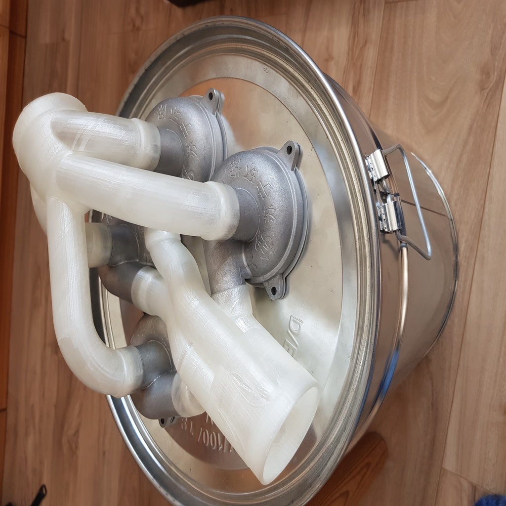
<p>This is the second stage of my <strong>cheap and easy DIY dual-stage dust cyclone project</strong> . <a href="https://www.prusaprinters.org/prints/54418-30l-workshop-dust-cyclone-stage-1-for-less-than-25">Click here to visit the first stage</a>. To be honest, I estimate that for a lot of use cases <a href="https://www.prusaprinters.org/prints/54418-30l-workshop-dust-cyclone-stage-1-for-less-than-25">stage one is "good enough"</a> and it has a far better price to performance ratio than this stage two you are looking at. So you might start out using stage one and then find out how much dust still ends up in your precious vacuum filters. In my experience no coarse dust at all and about 5-15% of the fine dust gets through which still is enough to clog the filters over time. Stage 2 to the rescue!</p><p>Technically this design should achieve a better precipitation than stage one by using smaller tube diameters, which lead to an accelerated airflow. The faster airspeed through smaller cyclone radiuses should, in turn, increase the circular forces on the dust particles which cause them to hit the walls, slow and drop inside the cyclone. In order to not hamper suction airflow too much, the design uses four cyclones runing in parallel, achieving an effective airflow equivalent to a 50mm tube.</p><h3>What you need:</h3><ul><li>4 x <a href="https://www.ebay.com/itm/173240570051">chinese aluminum cyclones</a> from ebay. Yes... you could print them yourself, too. But these critters are made from metal and to print out four like them would NOT be easy and cost a lot of filament and time. Given the cost of ~55€, I reckoned I could use my time more efficiently than redoing what is already available at reasonable cost.</li><li>1 x a 30 liters hobbock with 33cm diameter (<a href="https://www.ebay.com/itm/170925876047">I bought this one</a>) for 20€. It may be worth mentioning that this design should be mountable on any container with a flat top that features an unobstructed circular area with a diameter of at least 30cm.</li><li>max. 200-250g of filament (PLA will do, PETG or ABS are probably more durable)</li><li>a few grams of TPU or - if you have none or can't print that - some silicone sealant instead.</li><li>some <a href="https://www.amazon.de/dp/B005C99C5I?tag=tv-business-20">PTFE grease</a> is strongly recommended</li><li>a marking pen</li><li>a metal nibbler or a very good metal saw (if you use a metal hobbock). Nibblers can be had for less than 15€ at Aliexpress.</li><li>(optional) 10 screws or some glue or silicone to make the cyclones stay in place permanently.</li></ul><h3>Building steps:</h3><p>The pictures of this thing are lined up to represent the building steps below.</p><ol><li>Print the intake part first. If you are using an FDM (aka filament) printer, use the STL version that has "FDM" in the filename and <strong>read the printing instructions below!</strong></li><li>Once you have finished the intake,<i>carefully (read post-printing section below first!)</i> plug all four Cyclones into the intake like shown in the 5th picture. Make sure they are properly aligned straight to the surface of the bin lid in which they will sit later. Also take care that all of them go all the way into their respective opening. Use a bit of PTFE grease and carefully help them go in - using too much force will likely break your tubes.</li><li>Print four of the "hole placement helper" things. Put them around the four cyclones from below so that their arms meet in the middle. Use a junk chip of PLA, wood or cardboard and glue to connect them. Take your time and wait until the glue has cured completely!</li><li>remove the placement helper construction from the cyclones and place it on the lid of the hobbock like shown in picture #7.</li><li>Use the marker to mark the holes for the cyclones and cut them out like shown. Use the intake with its plugged-in cyclones to make sure all holes fit.</li><li>Print the TPU seals - using TPU filament, of course. If you can not print TPU, just skip them and use silicone in step 10.</li><li>Do NOT fix anything yet! No glue, no screws!</li><li>Now print the exhaust part. Again, if you are using a filament printer, use the STL with "FDM" in its name and <strong>read the printing instructions below!</strong>. There also is a section to read on removing the FDM support socket!</li><li>If you did everything right, the exhaust should fit on top with a little wiggling and rubbing. It can be a good idea to use one of the cyclones as a tool to push and turn and widen all sleeves so that they fit properly. Again, I recommend the use of PTFE grease.</li><li>Once all pieces have found their place you can use screws on the cyclone screw-holes and/or apply some silicone to achieve a tight fit of the cyclones to the lid.<br>The intake and exhaust opening diameters are 60mm. There is an additional 25° angled adapter provided in the downloads.<br>Please browse my other things to find proper adaptors for suction hoses.</li></ol><h3>Print instructions</h3><p><br><strong>Printer Brand: </strong>Anycubic</p><p><strong>Printer: </strong>All-metal Mega</p><p><strong>Rafts: </strong>optional</p><p><strong>Supports: </strong>No</p><p><strong>Resolution: </strong>0.2mm</p><p><strong>Infill: </strong>15%</p><p><strong>Filament:</strong> filamentum Extrafill PLA natural<br> </p><h3><strong>Notes</strong></h3><p><br><strong>Important:</strong> If you use a filament (FDM) printer, always use the STL version with "FDM" in the name! Do not let your slicer place supports because the FDM files are properly prepared to not need any additional supports.<br>If your slicer has a “<strong>print thin walls</strong>” setting (Cura has!) make sure it is <strong>enabled</strong>!</p><p>Use a brim of at least 1.5cm on intake and exhaust parts to make sure they do not come off the bed. Do not use a brim on the placement helper or TPU parts.</p><p>While the FDM intake part does not need any special treatment, the exhaust FDM file features an added base part which has some build plate bonding surface and lets the whole design print at an angle of 30°.<br>This little trick removes all need for support in the upper parts of the design. The exhaust is bonded to that printing base by a very thin ring which can easily be cut with a carpet knife.</p><h3>Post-Printing</h3><p><strong>Fitting the cyclone tubes into the printed sockets of the intake/exhaust</strong></p><p>The sockets of the printed parts are calculated for a tight fit. That means you must <i>thoroughly</i> clean out all of them with a sharp cutting knife or similar tool and fine sanding paper until they feel smooth and round to the finger and no grates are left inside.</p><p>After that put some grease (I recommend PTFE because it does not react chemically with plastic materials) into the sockets and ensure check the fit by <strong>carefully</strong> grinding each cyclone into their actual sockets for at least two or three times. If they refuse to go in, do not force but check if you have missed to remove some grates.</p><p><strong>Removing the support socket from the exhaust</strong></p><p>Although the connecting ring is only "one wall layer" thick, it was holding up pretty strong on my test print. You will probably need a heated blade or a slow-running grinder to cut it loose - it is a bit much for a simple carpet knife blade.</p>
With this file you will be able to print DIY fine dust quad cyclone (stage 2) for ~ 80€ with your 3D printer. Click on the button and save the file on your computer to work, edit or customize your design. You can also find more 3D designs for printers on DIY fine dust quad cyclone (stage 2) for ~ 80€.