DIY Desktop CNC
thingiverse
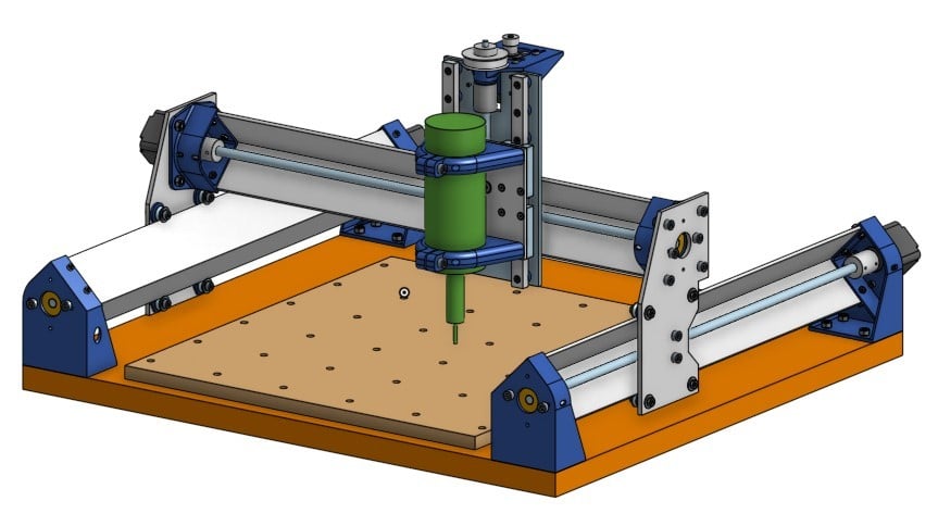
This CNC design was born from a YouTube video showcasing a similar project on the cusp of production.\r\nIt's the second CNC machine I've designed, both aiming for an easy-to-build desktop model at an affordable price point.\r\nTo date, it hasn't been built yet, but I'm confident that it will meet its goals with minimal hiccups.\r\n\r\nThe design utilizes 50mm thick aluminium angle and 625VV 'V' bearings for the X and Y rails. This rail and V bearing arrangement conveniently:\r\n---Provides a clear separation between the V bearings\r\n---Places the lead screw on the center line of the V bearings\r\n---Keeps the bearing support plates (100mm*4mm aluminium) very close to the lead screw center line\r\nLinear rails are used for the Z axis, ensuring that the spindle/router center line is as close as possible to the X plate and V bearings.\r\nThis X,Y and Z arrangement aims to minimize any lever arms that cause unwanted movements.\r\n \r\nNEMA17 stepper motors are used, with single start (2mm pitch) lead screws employed to maximize the limited torque from NEMA17. The Z axis utilizes a toothed belt reduction ratio of 16:60 to increase resolution and reduce torque requirements.\r\nThis setup will be slow but acceptable for a home desktop CNC like this. However, steppers can easily be upgraded to NEMA23 (a suitable adaptor is included) and 4 start (8mm pitch) lead screws used instead.\r\n\r\nThe longest lead screw is slightly less than 500mm, providing an effective X range of 390mm and Y range of 360mm. Z range is around 75mm. Anti backlash blocks are used throughout, with a 0.1mm allowance made for several layers of paper shim to ensure good alignment.\r\nIt would easily be possible to increase the X/Y size. If this is done, consideration should be given to strengthening the rails by epoxying (and/or bolting) an additional 40mm angle inside the 50mm angle.\r\n\r\n3D printed parts support the rails and stepper motors, as well as mounting the V bearings. 'Spacer Array' and 'Z Nut Spacer' should be printed at 0.1mm layer height, while all other parts can be printed at 0.2 or 0.3mm layer height.\r\npdf's of the X, Y and Z plates are included, which should be printed at actual size and used as a guide for drilling all the holes.\r\nBefore drilling the X and Y plates, assemble 2 625VV bearings either side of the aluminium angle and measure the bearing center distance. This should be 85.71mm or 85.71-5mm to the closest bearing surface. Note that the eccentrics allow +/-0.4mm of adjustment.\r\nIf necessary, make a minor adjustment to the spacing of the 4 bearing holes (8mm dia) on the X and Y plates.\r\n\r\nThe design was completed in Onshape, and anyone can visualize the design by following this link\r\nhttps://cad.onshape.com/documents/d5df1b483d27c4f3e0663c31/w/7176886e3c5335a6360f9906/e/ecab29bb5648e917ba3498c4\r\nUse right mouse+Alt to orbit and right mouse+Ctrl to pan.\r\nAll possible movements can be simulated in the 'Ass Total' tab by clicking and dragging the router. Or copy the design to your own workspace and modify as necessary.\r\n\r\nOne of the Onshape tabs shows a potential router spindle design using a brushless RC motor (MT Series 5206 320KV). This is very experimental, and it will be necessary to purchase a motor and make adjustments to the 3D printed part before proceeding.\r\n\r\n23/5/2019 605 bearings were incorrectly sized. 'Z Stepper Mount' and BOM updated.\r\n14/03/2020 It has come to my notice that 2" angle (1/8" thick) is sometimes easier to obtain. If there is any interest, I will produce a modified design to suit.
With this file you will be able to print DIY Desktop CNC with your 3D printer. Click on the button and save the file on your computer to work, edit or customize your design. You can also find more 3D designs for printers on DIY Desktop CNC.