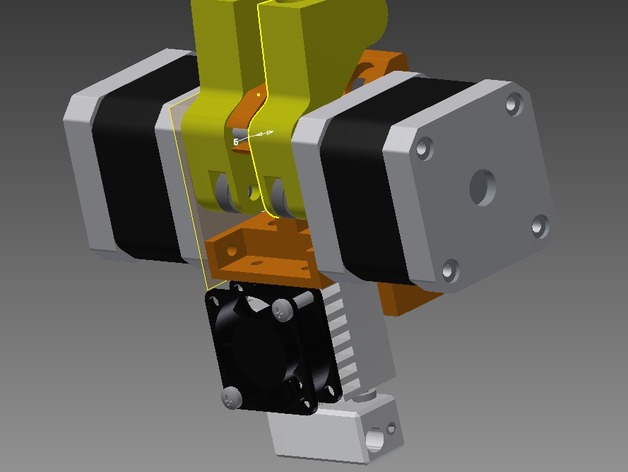
Direct filament drive for Cyclops extruder
thingiverse
The cyclops hot end from E3D is a fantastic concept, eliminating many problems with single-nozzle designs that incorporate multiple colors. This innovative approach is designed specifically for bowden style extruders which can be less reliable compared to direct drive configurations. To overcome this limitation, components were developed to enable the cyclops hot end to operate in a direct drive setup. Print Settings: - Printer: Home-built, measuring 600mm x 300mm x 300mm Rafts: No raft needed Supports: Irrelevant for this setup Resolution: .2mm precision printing required Infill: 100% fill density necessary Instructions to integrate the cyclops hot end into an existing printer: 1. First, print the main extruder chassis block. 2. Next, produce the levers for the lever pivot assembly. The levers are intended as a fix for issues with Extruder Lever 2 on the LH and RH sides. Details of the lever pivot assembly include: - A 5mm rod that serves as the lever's axis. - The ends of the rod are drilled and tapped to accommodate 3 mm screws. Removing One Screw from Each Stepper Motor: For mounting purposes, take out one assembly screw from each stepper motor. This action will allow attachment of the lever pivot. Step-By-Step Modifications: 1. Remove the threaded holes on the shaft side of the body's housing by drilling them. 2. To avoid filament obstruction, use a MK7 Filament drive wheel which can be purchased online. Make sure to shorten the stepper shafts so that they do not protrude beyond this assembly component. Assembly Components: - Long 3mm screws: Two such screws will be required for assembly, the ones I utilized originated from an old extruder. The Installation Process Involves: 1. Following instructions for assembling the cyclops hot end as intended. 2. Mounting the assembled hot end on the bottom of the Extruder chassis block with the 3 provided screws. 3. Secure PTF tubing through the cyclops extruder's heat blocks' 4mm holes by forcing it downwards using appropriate pressure. 4. Utilizing correct length and screw type for the bearings (using set screws) - assemble these to the extruder chassis block alongside the levers. 5. Pushing lever pivot throughout both lever units. Find adequate spring force, and place them appropriately between these assemblies. 6. Insertion of long 3mm socket head screws onto the motor attachments 7. Clamp or leverage must be utilized in assembling each screw in turns - do so to allow proper positioning of the parts while minimizing interference with each part. Testing Stage: - Perform test prints on the newly integrated setup. - Insure the extruder does not exceed standard speeds. Average operational range should fall under 10mm/s max. - Verify no speed-related complications or filament-related issues exist within the print cycle. In closing, take time to ensure the installation is successful before starting production printing; a few hours invested during testing will provide great dividends.
With this file you will be able to print Direct filament drive for Cyclops extruder with your 3D printer. Click on the button and save the file on your computer to work, edit or customize your design. You can also find more 3D designs for printers on Direct filament drive for Cyclops extruder.
