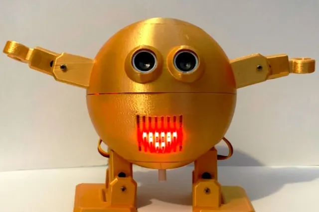
DingbOtto sphere humanoid robot
prusaprinters
For Mad Scientists, Evil Geniuses, and those who just like small robotsThis is a remix of the original Otto Humanoid variation. As well as having a rather smart spherical body he now has room for a much larger internal battery - up to a 18650 dual battery shield. There are also mountings for additional sensors such as an MPU6050 IMU and two extra LEDs.A number of variations are provided for by the design files:Two or four piece body construction. This changes how the pieces are supported during printing, and is purely cosmetic. The four piece version ends up with a better surface quality at the top and bottom of the body, but needs gluing.Armed or armless, but how can he cause mischief without hands?Servo motor MG90S, MG90D or SG92R. These are all similar, but not quite identical. Minor changes are needed in the positioning of the mounting holes and the space needed for the servo body.Built-in printing supports or add your own.Level of difficulty: ⭐⭐☆☆☆ Assembly can be a bit fiddly but nothing is difficult⏱Time to print? 2 days⏱Time to build? 2 hours✏Release Version: v1 (Internal development version: high)🔧instruction manual link? Use Otto Humanoid for now🧊3D files link? STL files available for printing, with STP and F3Z for easier editing💻Code link? Use Otto Humanoid for now📱Control with app? Compatible with the Otto app Part List3D Printed ComponentsSee the Fabrication section for which variations to pick. About 250g of filament is required - about 85m at 1.75mm diameter.1x Head (upper hemisphere)1x Body (lower hemisphere)2x Leg2x Foot2x Arm (unless armless)2x Hand (unless armless)Internal ComponentsAny links are provided as examples, not endorsements, and may not be the exact brand used by the designers. Ebay or far-East vendors such as BangGood are other possible, and probably cheaper, sources, and were used by the designers.6x MG90D/S or SG92R Servos (4 if armless)1 x Nano ATmega3281 x Nano I/O shield1 x USB-A to Mini-USB Cable1x MAX7219 8x8 LED matrix e.g. https://www.amazon.co.uk/HALJIA-Seamless-Cascadable-MAX7219-Display/dp/B06XDRSW4Z (use the square version with the SMD chip, not the rectangular version with the DIL chip such as at https://www.amazon.co.uk/iHaospace-MAX7219-Control-Display-Arduino/dp/B077P1CW1R )1 x Ultrasound sensor HC-SR041 x Buzzer e.g. https://cpc.farnell.com/multicomp-pro/mckpt-g1210-3916/piezo-buzzer/dp/SN36947 Must fit in a 12.5mm round hole.Up to 30 Female/Female Dupont Wires depending on sensors fitted, 15 or 20cm long, or connecting wires and crimping terminals. e.g. https://www.amazon.co.uk/Kamtop-Crimping-Connectors-0-1-1-0mm²-Connector/dp/B078K9DT691 x 18650 battery shield e.g. https://www.amazon.co.uk/diymore-Battery-Shield-Type-C-Raspberry/dp/B08B852L321x or 2x 18650 battery1 x Toggle Switch e.g. https://cpc.farnell.com/alps-alpine/spph410100/switch-pcb-dpst-latching-spph410100/dp/SW04790 Must fit in a 9mm square hole.Extra screws (M2 or M2.5 6mm)Clips to hold components. e.g. https://www.amazon.co.uk/TANCUDER-Mounting-Brackets-One-Side-Waterproof/dp/B087WSXT9F (200 is rather excessive - only 3 or 4 are needed). An STL file for a suitable clip is provided, but moulded ones are stronger.1x MPU6050 movement sensor (optional)2x LED with integrated resistor for 5V usage (optional) Tools3D printerSoldering iron - needed for internal battery shield and power switch connections. Dupont style push-on connections can be used for everything else.Computer running Arduino IDESmall Phillips screwdriver3D print finishing tools. e.g. knife, sandpaper, small drill or bradawl for clearing out holesFabricationSTL files for 3D printing are provided. If modifications are required then the STP or F3Z (Fusion 360) versions are easier to manipulate. Servo selectionIf the same servo type is used throughout then component selection is consistent and easy. However, servos can be mixed between the different parts, subject to the following rules:The head and arm servo names must match.The leg and foot servo names must match.The body servos are independent from other components. Sphere pieces3D printing a sphere cleanly is difficult. A number of choices are provided for:Hemisphere pieces are for a two part body. These print open side up so that the component mountings print cleanly, but this can lead to a poor surface quality on what becomes the highest and lowest parts of the body.Equator and pole pieces are for a four part body. The pole pieces print outside up, giving a better quality visual surface. The pole pieces are compatible with any servo equator piece. Because of the need for supporting the body pole piece to allow the internal mountings to print, the joining surface is likely to need sanding smooth after removing the supports. The head pole piece prints directly on the printer bed, so should always be smooth. The pole and equator sections need to be glued together. UHU All Purpose adhesive works very well for PLA, but the pieces should be clamped or taped in place while it dries.The join between the two halves is consistent across designs. It is possible to use a single hemisphere for one half and an equator plus pole for the other half. Foot piecesEach of the foot pieces for a given servo type is available in three versions:UnnamedEmbossed with "OTTO"Embossed with “DINGBOTTO”Printing supportAny file containing the word 'supported' has all necessary printing support included. No additional support needs to be added by the slicer. There are unsupported versions of all items as well for experts who want to optimise their printing process.Slicer settingsA medium resolution (0.2mm layer height) works well for most pieces. Using a finer layer height works better for the head pole and body pole pieces because of the angles of those surfaces.Wall thickness should be three layers (typically 1.2mm) and top and bottom thicknesses at least 1mm. An infill ratio of 20% works well for most pieces, but higher may be necessary for the body lower hemisphere to strengthen the grill over the LED matrix. Cura uses an infill pattern with a 20% setting, but switches to solid bars, which are stronger, at 30%. These are the only fragile part of the design, especially if pushed from inside the body. Take care when fitting the LED matrix into place.No raft is needed, but a 5mm brim helps prime the extruder and stop the part lifting during printing.Post printingNormal post printing, such as cobweb removal, is needed, but not much else. Close tolerance fits should be inspected and trimmed with a sharp knife if necessary. Key areas are:LED matrix clipsInside the eye sockets, where the HC-SR04 sensor should be a snug fit.Areas surrounding servo shafts.Hand-arm jointPainting?DingbOtto looks good straight off the printer, especially when using a silk textured metallic colour filament. Even standard white PLA looks good, in an under-stated sort of way.Sanding, using filler to hide the layer lines, resanding, high-fill primer/undercoat, fine sanding, second primer coat, metallic spray paint, very fine sanding, second paint coat, protective clear coat, and second clear coating each 3D printed piece is a lot of work, but can give a fantastic appearance. Follow all product instructions carefully, especially drying times, or the surface finish can be damaged easily through early mishandling.File version numbersWhat do the version numbers of each STL or STP file mean? Not much!They are related to the internal product development, but since one part might reach a high version number and then be saved with a different name it would then reset to version 1, so a low version number part might not have less development behind it than a high version number variation. Likewise, variations on some parts to allow the use of a different servo might be updated less often than the underlying design, so parts of the same 'generation' might have very different version numbers.Some parts have version numbers designed in, and those numbers are related across servo variations, regardless of how the file name version number may vary. e.g. As of early April 2021, the body underlying version is v30 and the head v16.Software / CodeCurrently, only the standard Otto software is usedDingbOtto is fully compliant with Otto Humanoid, so anything Otto Humanoid can do, DingbOtto can do cuter.ElectronicsDingbOtto uses the Arduino connectivity standardised by the Otto series. In addition the MPU6050 IMU can be connected to the SCL-SDA-5V-GND set of connectors. (SCL and SDA are common with the S pins for A4 and A5), and LEDs can be connected to D10 and/or A7. A7 can be used by some of the Otto software for monitoring battery voltage levels, so if this is needed, only one LED may be controllable.Assembly InstructionsGeneral considerations:All components are screwed into place, or held by a clip screwed to the case nearby, except for the touch sensor which should be held on the internal flat panel above the ultrasonic sensor by double-sided sticky tape. Two layers may be needed depending on the smoothness of the panel surface.Components mounted in the lower hemisphere should have a 12-15cm lead to connect them to the Nano I/O shield. Components in the upper half should have a 15-20cm lead. The longer the wires are, the easier the component placement is, but harder it is to fasten the two halves together.The LED matrix clips into place. If removal is necessary a fine screwdriver or similar implement should be used to prise the clip away from the matrix case, one side then the other. The hands are also a push-fit clip connection into the arms. It is easier to screw the arm servos into the arms before the hands are inserted but still possible afterwards. Important order considerations:The foot servo leads must be threaded through the side of the leg and the hole in the body before the leg servo is fastened into the body. Fastening the leg servo into place blocks the servo 3-pin connector from passing through this hole.The servo horn in the leg must be fastened to the leg servo in the body before the foot servo is fastened into the leg.We invested lots of time and resources to provide open source code, software and hardware, please support this project by just giving us a ❤ Like and share and you are welcome to be a part of this friendly community of robot builders, teachers and makers. Join today our Otto Builder community
With this file you will be able to print DingbOtto sphere humanoid robot with your 3D printer. Click on the button and save the file on your computer to work, edit or customize your design. You can also find more 3D designs for printers on DingbOtto sphere humanoid robot.