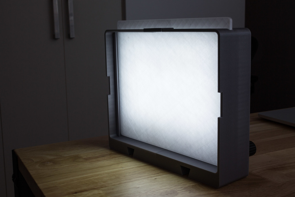
Dimmable LED softbox
prusaprinters
<p>Light up your desk with this dimmable LED softbox! With 3D printed diffuser and honeycomb light shaper.</p><p>Powered by a LiPo battery (4S-7S) with an XT-60 connector. It has rails on the bottom for adding mounts and accessories!</p><p>Designed to fit on the Prusa i3's bed: a 250mm by 210mm build area is required for best results.</p><p>A 240x200mm bed is okay if you don't need to print the honeycomb light modifier, or if you remove its two little handles.</p><p>A 210x130mm bed is okay if you don't want to print either the diffuser or the light modifier. You can make a diffuser using baking paper stretched over a cardboard frame instead, or design a diffuser that can be printed in two pieces.</p><p>Note: Slicing instructions are based on <a href="https://shop.prusa3d.com/forum/general-discussion-announcements-and-releases-f61/slic3r-prusa-edition-1-42-0-alpha3-t27105.html">Slicer PE 1.42-alpha3</a></p><h3>Post-Printing</h3><p><strong>Parts list</strong></p><p>Components:</p><ul><li>Mean Well dimmable DC-DC LED driver: LDD-1500LW, LDD-1200LW or LDD-1000LW (<a href="https://www.meanwell-web.com/content/files/pdfs/productPdfs/MW/LDD-l/ldd-l-spec.pdf">datasheet PDF</a>), I bought mine <a href="https://www.mouser.com/ProductDetail/MEAN-WELL/LDD-1500LW?qs=JK6Bpmia%2FmunLHBIWsj1oA%3D%3D">from Mouser</a></li><li>LED strip (white), I used 1 metre of it: <a href="https://www.banggood.com/5M-WhiteWarm-White-5630-SMD-Non-waterproof-300-LEDs-Strip-light-12V-p-922423.html">From banggood</a></li><li>Blade fuse holder: <a href="https://www.banggood.com/5Pcs-30A-Amp-Auto-Blade-Standard-Fuse-Holder-Box-For-Car-Boat-Truck-With-Cover-p-1384147.html">From banggood</a>. The fuse holder that the panel cutout is designed for is marked "JEF" inside the fuse cover, and I believe this is that model.</li><li>2A blade fuse (or source a single fuse locally): <a href="https://www.banggood.com/100Pcs-Blade-Fuse-Kit-2A-3A-5A-7_5A-10A-15A-20A-25A-30A-35A-p-919962.html">From banggood</a></li><li>20mm diameter circular snap-fit panel-mounted power switch</li><li>24AWG silicone wire (1m should be enough): <a href="https://www.banggood.com/1M-8101214161820222426-AWG-Silicone-Wire-SR-Wire-p-921159.html?ID=512910">From banggood</a>. Silicone-jacketed wire is nice because of its high temperature resistance. 26AWG would also work.</li><li>XT-60 male connector: <a href="https://hobbyking.com/en_us/nylon-xt60-connectors-male-female-5-pairs-genuine.html?affiliate_code=VLYQZVTEHHOROYT&_asc=4346988464">From HobbyKing</a> (buy them in pairs because you should have the female connector plugged into the male during soldering for heatsinking and alignment)</li><li>12mm 5k potentiometer with 1/4 inch shaft. The one I designed for was from my local hobby shop, and appears to be <a href="http://www.taiwanalpha.com.tw/products/4">Alpha brand</a>, however it's not on their current product list</li><li>2.5V voltage reference (<a href="https://www.ti.com/lit/ds/symlink/lm336-2.5-n.pdf">LM336-2.5 datasheet</a>)</li><li>3x10k trimpots, or 1/4 watt resistors</li><li>Circuit prototyping board that can be cut down to be around 20mm wide (score the board with a knife and snap it through a line of drill holes). You could skip this and build it rats-nest style.</li><li>220x150mmx0.5mm aluminium sheet. The thickness is not critical, but 0.5mm is easy to work with.</li><li>200mm velcro battery strap: <a href="https://hobbyking.com/en_us/graphene-velcro-battery-strap-200mm-x-20mm-3pcs.html?affiliate_code=VLYQZVTEHHOROYT&_asc=3667628912">from HobbyKing</a></li><li>Optionally, a little strip of velcro to anchor the battery tray to the lightbox</li></ul><p>Tools:</p><ul><li>Soldering iron</li><li>Tin snips and file/sandpaper for cleaning up burrs if you need to cut your aluminium sheet to size</li><li>Drill and 3mm drill bit for drilling aluminium plate and for cleaning up screwholes</li><li>Hot glue gun, or similar adhesive like double-sided foam tape, for securing electronics</li></ul><p>Fasteners:</p><ul><li>4x M3x10 cap head screws and nuts for securing fuse holder and XT-60 mount</li><li>4x M3x12 cap head screws and nuts for securing aluminium plate</li><li>Designed to use this kit of Suleve screws: <a href="https://www.banggood.com/442pcs-M3-Stainless-Steel-Hex-Head-Srews-Bolt-Nuts-Hexagon-Handle-Tool-Kit-p-1076216.html">From banggood</a></li></ul><p>Power:</p><ul><li>6-36V is the input range of the LED driver. The datasheet for it notes that the minimum step-down voltage as 3V, so you'll want to give it 12+ volts for a 12V LED strip to achieve maximum brightness. My driver only drops 0.4V, so I'm not sure if 3V is a typo for 0.3V.</li><li>If you choose to power it with a LiPo battery, use a 4S-7S battery. 3S works but won't maintain maximum brightness. <a href="https://hobbyking.com/en_us/zippy-compact-2200mah-4s-25c-lipo-pack.html?affiliate_code=VLYQZVTEHHOROYT&_asc=8797581965">Example 4S 2200mAh battery from HobbyKing</a>, example <a href="https://hobbyking.com/en_us/turnigy-battery-3000mah-4s-20c-lipo-pack-xt-60.html?affiliate_code=VLYQZVTEHHOROYT&_asc=3267160581">4S 3000mAh</a></li><li>If you're using a hobby LiPo, note that these batteries do not have built-in over-discharge protection, so they could be destroyed if you use the light to completely flatten them. Use a voltage alarm like <a href="https://hobbyking.com/en_us/hobbykingtm-lipo-voltage-checker-2s-8s.html?affiliate_code=VLYQZVTEHHOROYT&_asc=5024877411">this one from HobbyKing</a> to alert you, although you will want to cover those buzzers with tape to make them quieter for indoor use!</li><li>Any other DC supply in the right voltage range and with at least enough wattage to satisfy your LED strips will work, you can adapt a DC barrel jack to XT-60. An old laptop charger would be perfect. However, if you want to power it exclusively by AC, you may want to just redesign the electronics around a Mean Well AC-DC LED driver instead!</li></ul><p><strong>Electronics</strong></p><p>This softbox is built around the Mean Well LDD-1500LW DC-DC LED driver. This accepts 6-36V DC as input, and at full brightness will step down that input voltage in order to drive its output at 1500mA. See the full specifications here:</p><p><a href="https://www.meanwell-web.com/content/files/pdfs/productPdfs/MW/LDD-l/ldd-l-spec.pdf">https://www.meanwell-web.com/content/files/pdfs/productPdfs/MW/LDD-l/ldd-l-spec.pdf</a></p><p>There is also an LDD-1000L and LDD-1200L (with 1000mAh and 1200mAh peak output currents) that support the analog dimming used here, so choose the one that most closely matches your LED strip's current.</p><p>If your LED strips demand less current at their rated input voltage than the Mean Well is configured for, the strips could be overdriven and burn out. In order to prevent this, resistors can be added to the dimming control circuit in order to limit the maximum drive current.</p><p>Here's the dimming response curve from the LED driver's datasheet:</p><figure class="image"><img src="https://media.prusaprinters.org/media/prints/143776/rich_content/fb1d4aea-24a8-46a0-b8e7-525ef38252d9/sodo6dt.png#%7B%22uuid%22%3A%2293dad72b-77cb-4c86-96a8-5d4d22d499ba%22%2C%22w%22%3A1334%2C%22h%22%3A794%7D"></figure><p>I measured the current draw of my 1 metre of LED strips to be 1200mA, and I was using the LDD-1500, so I had to use the dimmer to limit the current (Iout) to 80% of maximum. Looking at the curve, that occurs at approximately 1.9V dimming voltage.</p><p>Here's the drive circuit:</p><figure class="image"><img src="https://media.prusaprinters.org/media/prints/143776/rich_content/db8477f2-0bfe-450f-b723-79a26df21cb7/tjz4kgf.jpeg#%7B%22uuid%22%3A%227c7129b3-94fa-440c-8676-22530e7c4048%22%2C%22w%22%3A1600%2C%22h%22%3A545%7D"></figure><p>The LM336 provides a 2.5V reference voltage, and this is divided by R2, the 5K potentiometer, and R3, to drive the dimming input of the LED driver. R1 limits the current through the system to avoid overdriving the voltage reference when the potentiometer is turned to 0.</p><p>Since I want to drive the dimming input to a maximum of 1.9V to limit it to 80% current, R2 needs to drop 2.5-1.9 = 0.6V. If you chose a driver whose output current matches or is lower than your LED strip current, R2 can be omitted.</p><p>The Mean Well driver has a large region at the bottom of the dimming curve where the light simply turns off, and this wastes a lot of the rotation of the potentiometer. So I want to drop 0.3V over R3 to cut off most of this region.</p><p>This leaves 2.5 - 0.6 - 0.3 = 1.6V to be dropped over the 5k potentiometer.</p><p>This allows us to compute the values of R2 and R3 like so:</p><p>R2 = 0.6 / 1.6* 5000 = 1875 ohms R3 = 0.3 / 1.6* 5000 = 937 ohms I used 1.8k for R2 and 1k for R3, since these are standard resistor values, but you could also use a trimpot for R2 and R3 and dial it in to your desired value.</p><p>Now it only remains to set R1 to control the current through the voltage reference. TI has an application note <a href="https://www.ti.com/vrefebook">all you need to know about voltage references</a> which explains how to choose this:</p><p>Rmin = (Vin_max - Vout) / (I_load_min + I_q_max) Rmax = (Vin_min - Vout) / (I_load_max + I_q_min)</p><ul><li>Vout is 2.5V (the reference voltage).</li><li>I_q_max for my voltage reference was 10mA</li><li>I_q_min was 0.4mA</li><li>My power supply is a 4S LiPo, which varies from 4.2* 4 = 16.8V (Vin_max) when fully charged to around 3.0* 4 = 12V (Vin_min) when dead</li><li>I_load_max occurs when the potentiometer is set to 0, so the current is limited by R2 and R3. In my case this was I_load_max = 2.5 / (1800 + 1000) = 0.00089A</li><li>I_load_min occurs when the potentiometer is set to 5k, so I_load_min = 2.5 / (1800 + 5000 + 1000) = 0.00032A</li></ul><p>Substituting these values in:</p><p>Rmin = (16.8 - 2.5) / (0.00032 + 0.01) Rmax = (12 - 2.5) / (0.00089 + 0.0004)</p><p>Rmin = 1386 ohms Rmax = 7364 ohms R1 needs to be somewhere inside that range (but avoid setting it to exactly Rmin since this would be driving the voltage reference right on its maximum rating!). I chose 5.6k.</p><p>So my final choices for driving 1200mAh of LEDs using the LDD-1500 with a 4S LiPo as a power source:</p><p>R1 = 5.6k R2 = 1.8k R3 = 1k </p><h3>Printing the lightbox body</h3><figure class="image"><img src="https://media.prusaprinters.org/media/prints/143776/rich_content/27e31f78-45a5-4643-b92f-2dd620ec0da9/printed_body.jpeg#%7B%22uuid%22%3A%220118bc78-5bec-4271-b306-3a7bf82950b3%22%2C%22w%22%3A2880%2C%22h%22%3A2556%7D"></figure><p>The lightbox should be printed in a neutral PLA colour. Black and silver are both good choices (I went with Prusament Galaxy Silver). White will work too, but it may be too translucent and make the whole lightbox glow. The printed weight is around 400 grams.</p><p>The lightbox is designed to be printed in two pieces which slot together with dovetails, and are finished off by gluing a cap to the join at the top. This limits the printing time for each half to around 13 hours each, to avoid overnight printing.</p><p>To print a side:</p><ul><li>Add Lightbox - left side.stl (or right side) to the build plate</li><li>Layer height 0.20mm</li><li>Infill 20% rectilinear</li><li>Supports "everywhere"</li><li>On "support material" tab, untick "auto generated supports"</li><li>Add a Support Enforcer to the part using "Lightbox - support enforcer.stl"</li></ul><p>Repeat this process to print the other side.</p><p>Finally, print "Lightbox - top face joiner.stl" with no supports.</p><h4><strong>Printing as a single piece</strong></h4><figure class="image"><img src="https://media.prusaprinters.org/media/prints/143776/rich_content/b55b9802-84af-45e5-823c-1c448cf83c13/print_as_one_piece.png#%7B%22uuid%22%3A%229fbc316c-d110-4919-a2cc-68fc8eb3d37e%22%2C%22w%22%3A1366%2C%22h%22%3A950%7D"></figure><p>Although the lightbox<i>can</i> be printed as a single piece, this will use up every millimetre of the 250x210mm bed, so bed adhesion may be a challenge, and the expected print time is 24 hours.</p><p>You can load up the "Lightbox single piece.3mf" file in Slic3r to get a pre-configured project. Otherwise:</p><ul><li>Add Lightbox single piece.stl to the build plate</li><li>Add a Support Enforcer to that using "Lightbox single piece - support enforcer.stl"</li><li>Drag the lightbox to bring the base of it as close to the front of the build plate as possible.</li><li>Layer height 0.20mm</li><li>Infill 20% rectilinear</li><li>Support "everywhere"</li><li>On "skirt and brim" tab, set Skirt loops to 0 (there isn't room for it)</li><li>On "support material" tab, untick "auto generated supports". Because there isn't enough room for the normal supports to fit on the build plate, reduce Pattern Spacing to 1.5mm (from the default of 2.0mm).</li></ul><p>Now slice the model and verify that there is no "toolpath detected outside build area" warning on the layers tab (caused by supports extending outside the build plate).</p><h3>Diffuser with customised infill</h3><figure class="image"><img src="https://media.prusaprinters.org/media/prints/143776/rich_content/3fe2c090-3044-422d-b558-fcc308866a29/diffuser_fill_-_rectilinear_5_percent.jpeg#%7B%22uuid%22%3A%22bc04a40d-9307-4eb9-b479-6c43da91d396%22%2C%22w%22%3A2880%2C%22h%22%3A1920%7D"></figure><p><strong>Diffuser with 5% Rectilinear transparent PETG infill</strong></p><figure class="image"><img src="https://media.prusaprinters.org/media/prints/143776/rich_content/e612de70-6297-4f73-8746-b4d4e59c3dc5/diffuser_fill_-_scattered_15_percent.jpeg#%7B%22uuid%22%3A%22f7ed4191-57e6-4b98-9830-866bc5e7bfd0%22%2C%22w%22%3A2880%2C%22h%22%3A1920%7D"></figure><p><strong>Diffuser with 15% "Scattered Rectilinear" transparent PETG infill</strong></p><p>This is a multi-material print, with a 0.1mm white PLA base, 4.8mm of transparent PETG infill, and a 0.1mm white PLA top. Because the bottom layer is so thin, it requires an extremely well calibrated bed level.</p><p>Traditional infill patterns build columns to join the bottom and top faces of a part. This is a problem for making diffusers, because those columns will block the horizontal transfer of light, and their shadows will be visible on the face of the diffuser.</p><p>Above you can see the result of filling the diffuser with 5% transparent PETG rectilinear infill, compared to a new infill type I'm calling Scattered Rectilinear, at 15%.</p><p>Scattered Rectilinear is like Rectilinear, except each layer runs at a random angle, random offset, and with random gaps between lines. Although the resulting infill is very weak, this eliminates the periodic structures of regular Rectilinear infill that are so visually disturbing. The end-result kind of looks like a natural fibre.</p><figure class="image"><img src="https://media.prusaprinters.org/media/prints/143776/rich_content/bcbf899f-8572-49b9-b302-49ccd8d3378c/spaghetti-q8.png#%7B%22uuid%22%3A%2246322fa5-23db-4a7c-bab8-f373c4041bf7%22%2C%22w%22%3A1920%2C%22h%22%3A1056%7D"></figure><p><strong>Who ordered the spaghetti?</strong></p><p><strong>Slicing the STL</strong></p><p>I've included presliced gcode for the Prusa i3 MK2, MK2.5 and MK3, but if you want to build it yourself, read on!</p><p>Building gcode with Scattered Rectilinear infill requires a customised version of Slic3r. I've compiled a binary for macOS here, based on 1.42.0-alpha3:</p><p><a href="https://github.com/thenickdude/Slic3r/releases/tag/version_1.42.0-beta-unidirectional">https://github.com/thenickdude/Slic3r/releases/tag/version_1.42.0-beta-unidirectional</a></p><p>To assemble this in Slic3r "Scattered Rectilinear edition", load the FilterBody.stl file, then add FilterHandle.stl to it as a child part. Place the part on the bed so the text faces upwards. Set these print settings:</p><ul><li>Layer height 0.1mm</li><li>First layer height 0.1mm</li><li>Material PETG</li><li>Infill density 15%</li><li>Infill pattern Scattered Rectilinear</li><li>Combine infill every 2 layers</li><li>2 bottom layers</li><li>2 top layers</li><li>The default "Start G Code" for the MK3 sets the extrusion multiplier to 95 using the M221 command. I found that 107 worked best for me, and I would recommend setting it to at least 100 in order to get a continuous first layer. MK2 and MK2.5 don't appear to do this.</li></ul><p>Add settings to the FilterHandle.stl part:</p><ul><li>10% rectilinear infill</li><li>3 tops and 3 bases</li><li>3 perimeters (it must be set to a different number of perimeters to the rest of the object)</li></ul><p>Add a colour change at 0.20mm and another one at 5.0mm.</p><p>Switch the display to "Colour Print" and verify that you have one solid layer, then a second solid layer with a new colour, followed by a whole bunch of spaghetti, then one solid layer, then another solid layer in a new colour.</p><p>The generated GCode will use PETG temperatures for the whole print, which we don't want. Open it up in a text editor and find this block near the start that sets the initial temperatures:</p><p>M104 S230 ; set extruder temp <br>M140 S85 ; set bed temp <br>M190 S85 ; wait for bed temp <br>M109 S230 ; wait for extruder temp </p><p>Replace that with:</p><p>M104 S215 ; set extruder temp for PLA <br>M140 S60 ; set bed temp for PLA <br>M190 S60 ; wait for bed temp <br>M109 S215 ; wait for extruder temp </p><p>And replace "M900 K45; Filament gcode" with "M900 K30; Filament gcode". Now search for "M600", which is the filament change command. The first occurrence looks like this:</p><p>; AFTER_LAYER_CHANGE<br>; 0.2 <br>M104 S240 ; set temperature<br>M140 S90 ; set bed temperature<br>M600 </p><p>We want to switch to PETG temperatures at this point without changing the bed temperature, so replace that with:</p><p>;AFTER_LAYER_CHANGE <br>;0.2 <br>M104 S240 ; set temperature <br>M600 <br>M900 K45 ; Filament gcode </p><p>Finally, search for M600 again and replace this:</p><p>;AFTER_LAYER_CHANGE <br>;5 <br>M600 </p><p>With:</p><p>;AFTER_LAYER_CHANGE <br>;5 <br>M104 S230 ; Start cooling to an acceptable PETG purge temperature<br>M600 <br>M104 S215 ; Continue cooling to PLA temperatures as the PLA layer begins </p><h3><strong>Printing instructions</strong></h3><p>Because the first layer is a thin 0.1mm layer of PLA, your bed must be very well levelled, e.g. with mechanical adjustment or by software. (I used the new 7x7 mesh bed levelling in the latest MK3S firmware). To tune the extrusion of the first layer to make it nicely continuous, you will need to tweak both the Flow and Live-Z settings.</p><p>You can use the <a href="https://www.thingiverse.com/thing:3141591">Customizable Bed Level Test</a> to tune your settings before attempting to print the diffuser. Configure it to print just a single 0.1mm layer.</p><p>Once the first layer successfully completes, the printer will beep at you for a filament swap. Eject the PLA, then wait at least 10 seconds for the nozzle to heat up to PETG temperatures before you start loading the transparent PETG. Note that after confirming that the filament change was successful, the printer will extrude an additional squirt of PETG before zooming off to begin the print - you may want to already have some tweezers ready to grab the waste filament as it departs. Otherwise it makes a big mess that gets baked into the diffuser.</p><p>Now a solid PETG layer will print, followed by the scattered rectilinear infill. The printer will sound a little different from normal while printing the infill, since printing at weird angles causes the axes to run at different rates.</p><p>Another solid PETG layer and now it's time to switch back to white PLA. You don't need to wait for the nozzle temperature to change this time, as it will only start cooling down to PLA temperatures after the entire filament swap is complete and printing the white PLA top begins.</p><p>Phew! If you were successful, now is the time to bask in your printing prowess!</p><p><strong>Bed adhesion note</strong></p><p>If you're printing on the i3 MK3 with the removable spring-steel plate, you've probably been picking up the plate and holding it by the corners to bend it to remove prints. This leaves fingerprints that ruin PLA adhesion, and you may not have noticed the effect of these if you haven't tried to print to the edges of the plate before. Since these don't clean off completely with isopropyl alcohol, I found I had to clean the bed with acetone to get rid of these and fix my adhesion at the edge. The difference was dramatic, and I no longer had problems with the corners of the diffuser lifting up.</p><h3>Honeycomb light modifier</h3><figure class="image"><img src="https://media.prusaprinters.org/media/prints/143776/rich_content/b6921cf5-4cce-48c0-83bc-a70bba3ea1ea/honeycomb_-_top.jpeg#%7B%22uuid%22%3A%224e489627-6d19-4b93-8051-f27892c56ca5%22%2C%22w%22%3A2880%2C%22h%22%3A1920%7D"></figure><p><strong>Honeycomb viewed from top - look how little light is visible!</strong></p><figure class="image"><img src="https://media.prusaprinters.org/media/prints/143776/rich_content/6d7733ea-0c66-436a-8bd6-a9435c6efc2f/honeycomb_-_front.jpeg#%7B%22uuid%22%3A%228a116193-ceef-461f-b17c-6fbda57f132e%22%2C%22w%22%3A2880%2C%22h%22%3A1920%7D"></figure><p><strong>Objects in front of the softbox get the full blast of light.</strong></p><p>The honeycomb light modifier restricts the angle of view of the softbox, shaping it into a tighter beam. This is useful when you don't want light to spill onto nearby objects that you're lighting separately.</p><p>Printed in black PLA. Avoid white or silver filament, as that would ruin the whole light blocking effect you're trying to achieve!</p><p>In Slic3r, load up "Light Modifier.stl". Set these settings:</p><ul><li>Layer height 0.2mm</li><li>Top layers 0</li><li>Bottom layers 0</li><li>Infill type Honeycomb</li><li>Infill Percentage 7%</li><li>Skirt loops 0</li></ul><p>Right click on the STL in the object tree and add a Modifier - "Light modifier handle slice zone.stl". Add to the modifier these settings:</p><ul><li>Infill 20% rectilinear</li><li>3 bottoms, 3 tops, 3 perimeters</li></ul><p>The handle modifier must be set to a different number of perimeters to the rest of the object, because otherwise the infill that Slic3r generates will overlap its perimeters and print as an overextruded mess. (Double check this using the layers view).</p><p>Orient the print so the little stubby handles are lying on the print-bed. This print spans the entire 250mm width of the Prusa i3 MK3, so you may need to click the "Arrange" button at the top to have Slic3r keep it all within the bed area for you.</p><h3>XT-60 panel mount assembly</h3><figure class="image"><img src="https://media.prusaprinters.org/media/prints/143776/rich_content/48077995-e6f4-4deb-b51b-ee9091bbf414/xt-60_panel_mount_insertion_demonstration.gif#%7B%22uuid%22%3A%226d1ba89c-23ff-4b8e-adb0-bff68f756558%22%2C%22w%22%3A580%2C%22h%22%3A435%7D"></figure><p>The XT-60 connector needs to be installed into the panel mount using a tap from a hammer. The original XT-60 connectors from HobbyKing are high quality nylon and should survive this process without a problem.</p><p>Because the pins of the connector will protrude out of the bottom of the panel mount once installed, be sure not to just stand the mount up on your desk to tap it in (you'll end up with two dents in your desk from the pins!). Instead, print two copies of the panel mount, and hold them together as a stack as shown above while you tap the connector in. The bottom mount will act as a protector for the pins.</p><p>The panel mount prints without supports, at 100% infill and 0.1mm layer heights. PLA works fine. You may want to add a brim to increase bed adhesion.</p><h3>Installing the components</h3><figure class="image"><img src="https://media.prusaprinters.org/media/prints/143776/rich_content/28f6d17f-a2c9-4293-9079-d8e4cdff7a95/electronics_installation.jpeg#%7B%22uuid%22%3A%22f6e610ef-bf58-4d3c-877b-fc912de8a3fd%22%2C%22w%22%3A2880%2C%22h%22%3A1920%7D"></figure><p>Prepare your aluminium mounting plate by cutting it to size and drilling the 3mm mounting holes (in a 200mm x 130mm grid as shown in the PDF). Clean the plate off with isopropyl alcohol, then trim and stick your LED strips to it (I used 5 rows of 4 units). Solder wires to put the strips in parallel with each other (+ to +, - to -), taking care not to allow solder to spill off the side of the strip and short it to the plate.</p><p>Use your 3mm drill to clear out the sacrificial bridges that are filling the 4 LED plate mounting holes (you can drill from the front side to use the inside of the mounting posts as a drill bit guide). Thread the longer cap head screws in from the back, slot the plate down on top of them, and secure with 4 M3 nuts. Ensure that the bottom edge of the plate does not foul the XT-60 connector.</p><p>Install the XT-60 connector and blade fuse holder into the panel using the shorter M3 screws and M3 nuts. You can use the screw to grab the nuts and pull them into the nut wells - but be sure to align the nut correctly with the well as you do so. Install the power switch into the panel (it should be a snap fit). Slide the potentiometer shaft through and secure with a nut on the front side.</p><p>Follow the circuit diagram from the "post-printing" section to add the resistors and the voltage reference to your prototyping board.</p><p>Now solder wires between the panel components and LED strips and the circuit board.</p><p>Secure the completed board and the LED driver to the bottom of the case (I used hot glue to do so, but you could use double-sided foam tape). Tuck any loose wires behind the mounting plate - everything must sit clear of the slot where the diffuser will slide in from the top of the case.</p><p>Note that during operation the aluminium plate will heat up to around 50-60 degrees Celsius with the diffuser installed.</p><p>Install a 2A blade fuse into the fuse holder.</p><p>Finish assembly by gluing the joiner cap to the top of the lightbox (where there are two halves flapping in the breeze with no dovetail to secure them). I used medium CA and CA activator to get an instant bond.</p><p>Use a multimeter across the rails of one of the LED strips to verify that the strip isn't receiving more than its rated voltage (probably 12V) when the dimmer control is set to 100%.</p><h3>Battery carrier tray</h3><figure class="image"><img src="https://media.prusaprinters.org/media/prints/143776/rich_content/3dc39563-6b08-416e-82cb-ada8d5019d6f/battery_tray.jpeg#%7B%22uuid%22%3A%22833d2422-fac9-4f3d-b7a9-8c94691f735e%22%2C%22w%22%3A2880%2C%22h%22%3A1920%7D"></figure><p>This one is an easy print. PLA, 0.2mm layer height, no supports.</p><p>Thread the velcro battery strap through the included holes. You may need to add a thin strip of velcro to the side of the tray (as shown above) to hold the tray securely against the lightbox when installed.</p>
With this file you will be able to print Dimmable LED softbox with your 3D printer. Click on the button and save the file on your computer to work, edit or customize your design. You can also find more 3D designs for printers on Dimmable LED softbox.