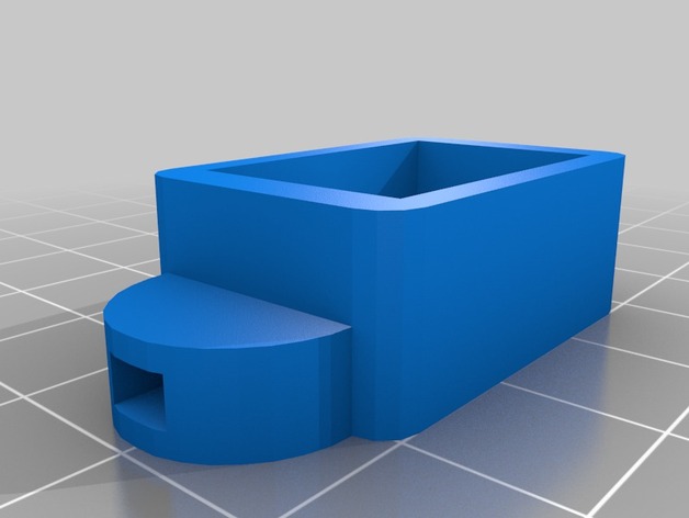
Digital voltmeter case
thingiverse
A Basic Design for a Three-Digit Seven-Segment Digital Voltmeter System The objective of this project is to create a simple and functional three-digit seven-segment digital voltmeter that can accurately display voltage readings. The system will consist of a microcontroller, a 7-segment display module, and a voltage sensing circuit. To start with, we need to select the components for our design. For the microcontroller, we'll use an Arduino board or similar, which is widely available and easy to work with. The 7-segment display module will be connected to the microcontroller using a digital interface such as I2C or SPI. Next, we'll design the voltage sensing circuit. This will involve selecting a suitable op-amp, resistors, and capacitors to ensure accurate and stable voltage readings. We'll also add a protection circuit to prevent damage from overvoltage conditions. Once the hardware is assembled, we'll write the code for the microcontroller to read the voltage from the sensor, convert it to a three-digit display format, and send the data to the 7-segment display module. The display will show the voltage reading in volts (V), with leading zeros if necessary. To ensure accuracy, we'll calibrate the system by taking multiple readings of known voltages and adjusting the code accordingly. This process will help us fine-tune the system for optimal performance. The completed system will be a reliable and easy-to-use three-digit seven-segment digital voltmeter that provides accurate voltage readings with minimal calibration required.
With this file you will be able to print Digital voltmeter case with your 3D printer. Click on the button and save the file on your computer to work, edit or customize your design. You can also find more 3D designs for printers on Digital voltmeter case.
