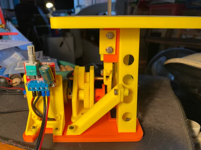
Die Filer 5.0
prusaprinters
Preparation:Start with the base, which now has slots for component adjustment. It's got chamfered slots for flat head screws too so it should sit flat on a table when it's all assembled.Motor Mount Lower gets 4: M3 x 5mm heatset inserts on its bottom and 2: M3 x 5mm heatset inserts on top.A Frame gets 2: M4 x 5mm heatset inserts on the bottom, 2: M4 x 5mm heatset inserts on the sides 2: M4 heatsets on top and 2: M4 heatsets on the front where the Cylinder will attach.Gearbox gets 3: M3 x 5mm heatset inserts pressed in from the bottomCrank Disk gets 1: M4 x 5mm heatset insert into the face where the shoulder bolt goes. Make sure it's just flush with the surface and plastic is cleared away so that the metal of the shoulder bolt contacts the metal of the insert. Crank Disk gets a pair of M3 x 4mm heatset inserts in its mounting collar. Output Gear has a fairly small collar and not much room for heatset inserts so I suggest using 2: M3 x 4mm inserts and pressing them in backwards so that the knurled part goes in first to get maximum strength. Once the part has cooled try to push a 5mm shaft through to make sure the heatset inserts clear the mounting shaft. If there seems to be an obstruction use a hand drill and a 5mm bit but run the drill in **reverse** to push obstructions back and to avoid tearing out the inserts. Once the drill goes through backwards then it's safe to run it forward to clear out any chips.Pinion has room for one or two: M3 x 4mm heatset inserts. Drill the pinion out if it won't fit on the shaft of the motor you pick.Top Plate gets 1: M4 x 5mm heatset insert in one corner bay. Leave the two holes near the center open.Insert Retainer gets 2: M3 heatset inserts; try to press them in from the flat side of the plateUpper and Lower Stiffeners get 1: M4 x 5mm heatset insert apiece.Controller Bracket gets 2: M3 x 5mm heatset inserts in the bottom. As for the circuit board mounting holes I just hand tap them as needed depending on the controller used.Hardware:In addition to the M3 and M4 heatset inserts you'll need:1: 5mm dia x 50mm length of brass rod; I prefer brass because it's easy to reduce diameter if it doesn't fit bearings. Chuck it in a drill and use some #360 grit sandpaper to reduce the diameter as needed.1: 5mm dia x 40mm length of brass rod.4: 5mm id x 16mm od bearings1: 5mm id x 8mm od bearing1: M4 shoulder bolt with a 5mm dia x 1omm long shank Assembly:Start with the gearbox: press in 4: 5mm id x 16mm od bearings. Next slide in a 5mm shaft from the motor end, capturing the Output Gear, the other bearing and finally the Crank Disk. End of shaft must not extend beyond end of Crank Disk. The other end of the shaft should stick out the motor end just enough to attach a shaft collar.Fasten the Output Gear and Crank Disk to the 5mm shaft with M3 x 3mm setscrews.Tap the Conn Rod's top end M4Press the small bearing into the bottom end of the Conn Rod, then slide the shoulder bolt through and thread it onto the Crank Disk.Slide the other 5mm shaft through the top set of bearings, capturing the Idler Cluster, making sure it lines up and meshes with the Output Gear. Shaft should be just long enough to attach shaft collars on either end.Press the Pinion onto the motor and fasten it on with M3 x 3mm setscrews.Attach the gearbox to the Base with flat head screws; pick a midpoint in the mounting slots and just finger tighten the bolts for now.Attach the lower Motor Mount and fasten it loosely as well.Attach the motor and loosely fasten Motor Mount Upper.Now slide everything around until there's good engagement between the Pinion and the Idler Cluster and fasten everything down. The geartrain should turn without resistance; if there is any, move the motor and pinion slightly until all runs effortlessly.Thread the four holes in the sides of the Cylinder M4Attach Cylinder to A Frame with M4 flat head screwsLay the Piston in the Cylinder, then fasten the two Piston Keepers with M4 x 8mm SHCS, making sure Piston slides freely. If the bolts poke into the Piston, use washers to pull their ends clear.Attach the A Frame to the Base, making sure the top of the Conn Rod slides into the bottom of the Piston. Fasten this joint with an M4 x 12mm bolt. Don't overtighten this: the joint has to pivot freely. Use a dab of Loctite if necessary. Bolt tje A Frame in place and then bolt on Lower Stiffener.Bolt on bottom of Upper StiffenerAttach Insert Retainer to the underside of the Top Plate with 2: M3 x 10mm flat head screwsAttach Top Plate to top of A Frame and Upper Stiffener with 3: M4 x 10mm flat head screws.As for wiring you're on your own but I recommend a 12v 2A PWM motor controller. Make sure the motor is wired up so that the direction of Crank Disk rotation tends to tighten, rather than loosen the Shoulder Bolt that connects to the Conn Rod. Nag me if I left anything out! I'll post a video when I find where I put the camera!
With this file you will be able to print Die Filer 5.0 with your 3D printer. Click on the button and save the file on your computer to work, edit or customize your design. You can also find more 3D designs for printers on Die Filer 5.0.
