desk lamp clock
prusaprinters
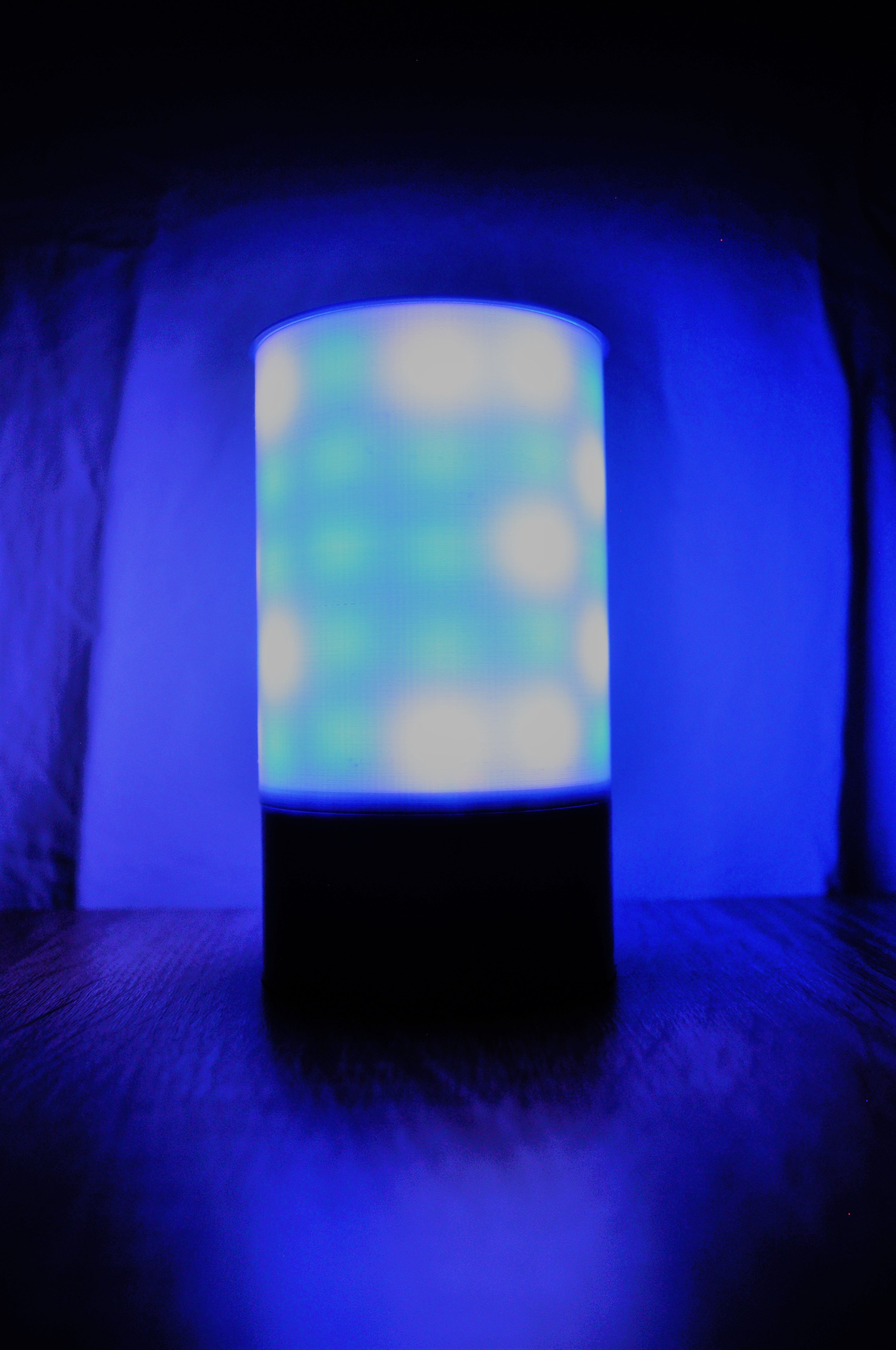
<p>I have put a lot of work in to this. I hope that you give it al like. The manual is coming.</p> <h3>Print instructions</h3><h6># Desk lamp clock</h6> <p>Everything need to be printed at 20%. This lamp is makes use from WS2812B led, I have used 60 of these. There is a matrix made of these led's. The matrix has a height of 5 led's and a width of 12 led's. and by using a DS3231 I am able to read the time and to print it on the matrix. The controller from the matrix is a arduino nano.</p> <p>The hole design is extremely simple so that it cannot go rong.<br/> All the parts need to be printed at 20% or higher, the ring need to be printed at 100%.</p> <h5>This is the code to set the time on the DS3231:</h5> <p>// DS3231_Serial_Easy<br/> // Copyright (C)2015 Rinky-Dink Electronics, Henning Karlsen. All right reserved<br/> // web: <a href="http://www.RinkyDinkElectronics.com/">http://www.RinkyDinkElectronics.com/</a><br/> //<br/> // A quick demo of how to use my DS3231-library to<br/> // quickly send time and date information over a serial link<br/> //<br/> // To use the hardware I2C (TWI) interface of the Arduino you must connect<br/> // the pins as follows:<br/> //<br/> // Arduino Uno/2009:<br/> // ----------------------<br/> // DS3231: SDA pin -> Arduino Analog 4 or the dedicated SDA pin<br/> // SCL pin -> Arduino Analog 5 or the dedicated SCL pin<br/> //<br/> // Arduino Leonardo:<br/> // ----------------------<br/> // DS3231: SDA pin -> Arduino Digital 2 or the dedicated SDA pin<br/> // SCL pin -> Arduino Digital 3 or the dedicated SCL pin<br/> //<br/> // Arduino Mega:<br/> // ----------------------<br/> // DS3231: SDA pin -> Arduino Digital 20 (SDA) or the dedicated SDA pin<br/> // SCL pin -> Arduino Digital 21 (SCL) or the dedicated SCL pin<br/> //<br/> // Arduino Due:<br/> // ----------------------<br/> // DS3231: SDA pin -> Arduino Digital 20 (SDA) or the dedicated SDA1 (Digital 70) pin<br/> // SCL pin -> Arduino Digital 21 (SCL) or the dedicated SCL1 (Digital 71) pin<br/> //<br/> // The internal pull-up resistors will be activated when using the<br/> // hardware I2C interfaces.<br/> //<br/> // You can connect the DS3231 to any available pin but if you use any<br/> // other than what is described above the library will fall back to<br/> // a software-based, TWI-like protocol which will require exclusive access<br/> // to the pins used, and you will also have to use appropriate, external<br/> // pull-up resistors on the data and clock signals.<br/> //</p> <h3>include <DS3231.h></h3> <p>// Init the DS3231 using the hardware interface<br/> DS3231 rtc(SDA, SCL);</p> <p>void setup()<br/> {<br/> // Setup Serial connection<br/> Serial.begin(115200);<br/> // Uncomment the next line if you are using an Arduino Leonardo<br/> //while (!Serial) {}</p> <p>// Initialize the rtc object<br/> rtc.begin();</p> <p>// The following lines can be uncommented to set the date and time<br/> //rtc.setDOW(WEDNESDAY); // Set Day-of-Week to SUNDAY<br/> //rtc.setTime(12, 0, 0); // Set the time to 12:00:00 (24hr format)<br/> //rtc.setDate(1, 1, 2014); // Set the date to January 1st, 2014<br/> }</p> <p>void loop()<br/> {<br/> // Send Day-of-Week<br/> Serial.print(rtc.getDOWStr());<br/> Serial.print(" ");</p> <p>// Send date<br/> Serial.print(rtc.getDateStr());<br/> Serial.print(" -- ");</p> <p>// Send time<br/> Serial.println(rtc.getTimeStr());</p> <p>// Wait one second before repeating :)<br/> delay (1000);<br/> }</p> <h4>For this code you have to download a driver, you are able to find it at the website that is in the code.</h4> <h4>This is the main code, you upload this code after you did the first one.</h4> <h3>include <DS3231.h></h3> <h3>include <Adafruit_GFX.h></h3> <h3>include <Adafruit_NeoMatrix.h></h3> <h3>include <Adafruit_NeoPixel.h></h3> <h3>include <Fonts/TomThumb.h></h3> <h3>ifndef PSTR</h3> <h3>define PSTR // Make Arduino Due happy</h3> <h3>endif</h3> <h3>define PIN 2</h3> <p>// MATRIX DECLARATION:<br/> // Parameter 1 = width of NeoPixel matrix<br/> // Parameter 2 = height of matrix<br/> // Parameter 3 = pin number (most are valid)<br/> // Parameter 4 = matrix layout flags, add together as needed:<br/> // NEO_MATRIX_TOP, NEO_MATRIX_BOTTOM, NEO_MATRIX_LEFT, NEO_MATRIX_RIGHT:<br/> // Position of the FIRST LED in the matrix; pick two, e.g.<br/> // NEO_MATRIX_TOP + NEO_MATRIX_LEFT for the top-left corner.<br/> // NEO_MATRIX_ROWS, NEO_MATRIX_COLUMNS: LEDs are arranged in horizontal<br/> // rows or in vertical columns, respectively; pick one or the other.<br/> // NEO_MATRIX_PROGRESSIVE, NEO_MATRIX_ZIGZAG: all rows/columns proceed<br/> // in the same order, or alternate lines reverse direction; pick one.<br/> // See example below for these values in action.<br/> // Parameter 5 = pixel type flags, add together as needed:<br/> // NEO_KHZ800 800 KHz bitstream (most NeoPixel products w/WS2812 LEDs)<br/> // NEO_KHZ400 400 KHz (classic 'v1' (not v2) FLORA pixels, WS2811 drivers)<br/> // NEO_GRB Pixels are wired for GRB bitstream (most NeoPixel products)<br/> // NEO_RGB Pixels are wired for RGB bitstream (v1 FLORA pixels, not v2)</p> <p>// Example for NeoPixel Shield. In this application we'd like to use it<br/> // as a 5x8 tall matrix, with the USB port positioned at the top of the<br/> // Arduino. When held that way, the first pixel is at the top right, and<br/> // lines are arranged in columns, progressive order. The shield uses<br/> // 800 KHz (v2) pixels that expect GRB color data.<br/> Adafruit_NeoMatrix matrix = Adafruit_NeoMatrix(12, 5, PIN,<br/> NEO_MATRIX_TOP + NEO_MATRIX_LEFT +<br/> NEO_MATRIX_COLUMNS + NEO_MATRIX_ZIGZAG,<br/> NEO_GRB + NEO_KHZ800);<br/> DS3231 rtc(SDA, SCL);</p> <p>const uint16_t colors[] = {<br/> matrix.Color(255, 255, 255)<br/> };</p> <p>void setup() {<br/> rtc.begin();<br/> matrix.setFont(&TomThumb);<br/> matrix.begin();<br/> matrix.setTextWrap(false);<br/> matrix.setBrightness(100);<br/> matrix.setTextColor(colors[0]);</p> <p>}</p> <p>int x = matrix.width();<br/> int pass = 0;</p> <p>void loop() {<br/> matrix.fillScreen(255);<br/> matrix.setCursor(x, 5);<br/> matrix.print(rtc.getTimeStr());<br/> if(--x < -35) {<br/> x = matrix.width();<br/> if(++pass >= 1) pass = 0;<br/> matrix.setTextColor(colors[pass]);<br/> }<br/> matrix.show();<br/> delay(100);<br/> }</p>
With this file you will be able to print desk lamp clock with your 3D printer. Click on the button and save the file on your computer to work, edit or customize your design. You can also find more 3D designs for printers on desk lamp clock.