Delta-P MMU2 IR for BEAR
prusaprinters
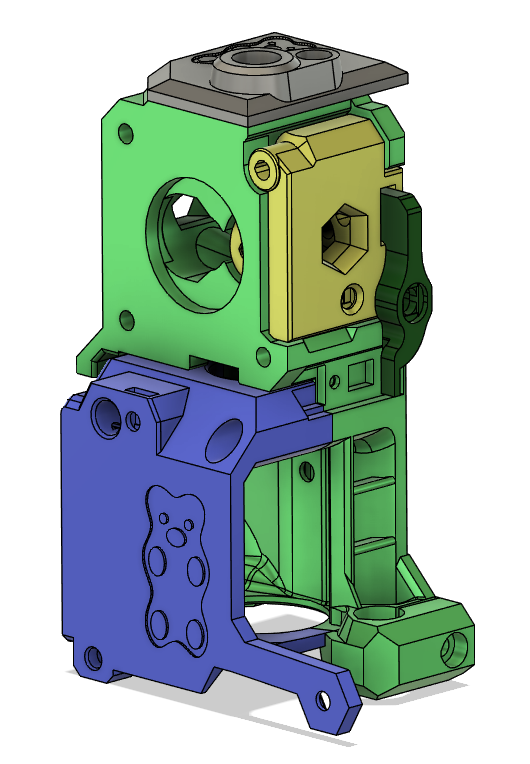
<p>This is a MMU2 IR sensor mod for the BEAR Extruder. It is a derivative of the MMU2 IR sensor on the Delta-P Extruder.</p> <p>Bear Extruder:<br/> <a href="https://github.com/gregsaun/bear_extruder_and_x_axis/releases">https://github.com/gregsaun/bear_extruder_and_x_axis/releases</a></p> <p>Delta-P Extruder:<br/> <a href="https://www.prusaprinters.org/prints/3091-delta-p-extruder">https://www.prusaprinters.org/prints/3091-delta-p-extruder</a></p> <p>UPDATE September 2 2020:<br/> *Door modified again to hopefully fix interference with motor bolt for good.</p> <p>UPDATE April 14 2020:<br/> <em>Door modified to remove interference with motor bolt.</em>Added an optional extruder body with a pocket for a 1050ZZ bearing. Useful if you run a pulley box and want extra support for the pulley shaft. The bearing pocket requires supports to print!</p> <h3>Print instructions</h3><p>NOTE!!!!<br/> This sensor mod requires:</p> <p>Custom IR Sensor PCB<br/> or<br/> Custom Firmware</p> <p>If you don't enjoy tinkering with and modding your printer, this might not be the best option for you.</p> <h3>Benefits:</h3> <p>Much easier to calibrate<br/> Can open idler door without loosing calibration<br/> No cumbersome chimney</p> <h3>Print instructions:</h3> <p>PETG<br/> 4 perimeters<br/> .2mm layers<br/> Lever MUST be printed in IR opaque material!</p> <h3>Required hardware:</h3> <p>In addition to hardware needed to build a standard BEAR extruder, you will need:<br/> 1x spring from a ballpoint pen<br/> 1x 3mm x 8mm steel shaft<br/> 1x 3mm locknut<br/> 1x 4mm OD 2mm ID 16mm long PTFE tube</p> <p>You also need the melt-in threaded insert and PTFE connector included with the stock Prusa MMU2 kit.</p> <h3>Assembly instructions:</h3> <p>Assemble per the BEAR extruder assembly instructions, substituting the parts included here for the standard BEAR parts.</p> <p>Install the IR sensor on the side of the extruder body as shown in the pictures.</p> <p>Install the Lever onto the Door as shown in the cross section picture.</p> <p>Install the melt-in threaded insert and PTFE holder into the top cover.</p> <p>Chamfer the ID of both ends of the 16mm long PTFE and insert into top of extruder before screwing down the top cover.</p> <h3>Sensor Configuration:</h3> <p>PLEASE READ CAREFULLY<br/> The sensor signal is inverted, therefore custom firmware OR a custom IR sensor is required.</p> <p>Click here for custom firmware:<br/> <a href="https://github.com/teookie/MK3_3.8.1_INVERTED_IR/releases">https://github.com/teookie/MK3_3.8.1_INVERTED_IR/releases</a></p> <p>OR</p> <p>Click here for custom IR sensor:<br/> <a href="https://easyeda.com/teookie/inverted-ir-sensor">https://easyeda.com/teookie/inverted-ir-sensor</a></p> <p>One or the other (custom firmware or custom sensor) is required; NOT BOTH. Pick the method that seems easiest to you. Both methods work. I recommend using the custom firmware first to see if you like this mod, and then switching to custom sensor later.</p> <p>If you choose to use the stock sensor (along with the custom firmware), you will need to remove the 90 degree header and either replace it with a straight header, or directly solder the wires onto the board.</p> <p>Custom Firmware note:<br/> The provided custom firmware also changes the default uSteps and eSteps for your printer. This will ONLY come into play if you do a HARD RESET of your printer (hold down the button while the printer boots, and select "All data"). In that case, you will need to use gcode to set the correct uSteps and eSteps after the hard reset.</p> <p>For 1:1 drive extruder (standard for BEAR):<br/> M350 E32<br/> M92 E280<br/> M500</p> <p>For 3.5:1 drive extruder (vertigo pulley box):<br/> M350 E16<br/> M92 E490<br/> M500</p> <p>Send M503 to verify settings are correct.</p> <p>Sensor Calibration Procedure:<br/> -Ensure bontech gears are clear of filament<br/> -Back out the lever screw so that the flag is completely outside of the IR sensor gate<br/> -Use the sensor status menu on LCD to verify IR sensor is reading "1"<br/> -Slowly turn in the lever screw just until the sensor state changes to "0"<br/> -Preheat hotend to 215° C<br/> -Use octoprint or a terminal to rotate the extruder motor<br/> -Verify that the sensor state remains at "0" for a full revolution of the bontech gears; if state fluctuates between 0 and 1, turn in the screw a small amount at a time until it is solidly "0" for a full revolution.<br/> -Turn the lever screw in an additional 1/16 turn<br/> -Calibration complete</p>
With this file you will be able to print Delta-P MMU2 IR for BEAR with your 3D printer. Click on the button and save the file on your computer to work, edit or customize your design. You can also find more 3D designs for printers on Delta-P MMU2 IR for BEAR.