Customizable 3D Tolerance Test
thingiverse
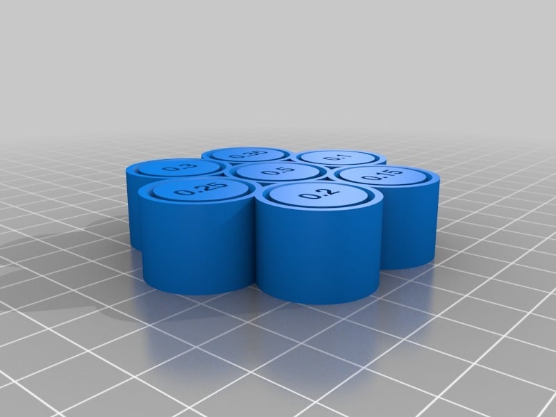
NOTICE TO STREAMLINE 3D USERS: Several users reported that S3D fails to slice this model accurately, and I was able to replicate the issue, with the 0.2 part fused at about Z=10mm http://i.imgur.com/99Qa9SV.png. If you experience this problem, try one of these workarounds (all worked for me): 1) Rotate the part on the Z axis by 90 degrees, or 2) Click Mesh | Separate Connected Surfaces before slicing. This test allows you to verify your printing process's accuracy and determine the optimal clearance between moving parts (e.g. hinges). It was inspired by this Maker's Muse video https://youtu.be/TYuLVN3YHw8 and designed with OpenScad (source file included here). The test enables you to test up to 7 different clearances of your choice. Each clearance is tested using a cylinder and a rod that have the specified clearance between them. After printing, examine which of the clearances resulted in free-moving parts, which can be freed by breaking them in using the screwdriver slot at the bottom, and which are simply stuck. Notes: * The model doesn't test first-layer tolerance, which is typically more problematic due to 'squashing' it against the bed and always has ample clearance on the first layer. * Each cylinder contains an overhang of 45%, used to keep rotating centers from falling out. * Clearances are measured horizontally, on the x,y plane, parallel to printed layers. As a result, actual clearance at overhang sections is lower, but horizontal clearance of each layer matters most. * With my 3D printing process (FFCP, PLA, S3D), I can release 0.2mm clearance but not 0.15mm clearance. To customize this test, click on the Customizer button in this page and change model parameters.
With this file you will be able to print Customizable 3D Tolerance Test with your 3D printer. Click on the button and save the file on your computer to work, edit or customize your design. You can also find more 3D designs for printers on Customizable 3D Tolerance Test.
