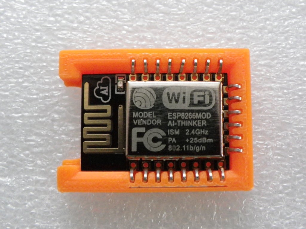
Customisable Module Socket for ESP8266 HC-05 etc
prusaprinters
<p>I've tried to make a customizable socket to fit any module you are trying to Program such as the ESP8266 wifi module or a HC-05 bluetooth module. Prity much any module that is based on being a board to be surface mounted.</p><p>The open SCAD file assumes that the left and right sides are mirrored and that if there are pins along the top then they are mirrored to the bottom.</p><p>The pins were sourced from a bag of different IC sockets. I broke apart the socket to recover the pins, then Straightened the legs of the pins. I found that sockets designed as through hole worked better for these sockets even if I intended the socket to be surface mounted.</p><p>In the end I used pins from a 84 pin PLCC socket search for "PLCC IC Socket" I chose a socket with through hole pins and a pin spacing of 2.54mm / 0.1 inch</p><p>The Open SCAD file can generate SVG files with the outline of the socket any holes needed and the placement of any copper pads. With that you will be able to then generate your own custom parts for your favorate PCB design software. Customizer can not work with generating SVG files so you would need to use open SCAD instead.</p><p>Also the Open Scad file can generate abase board to cover any off set pins.</p><p>Both these functions are experimental so don't rely on the default settings in the file.<br>I think for some pins the socket might need to be built in 3 parts</p><p>let me know what you think.</p><h3>Print Settings</h3><p><strong>Printer:</strong></p><p>CTC creator</p><p> </p><p><strong>Rafts: </strong></p><p>No</p><p><strong>Supports:</strong></p><p> </p><p>No</p><p> </p><p><strong>Resolution: </strong></p><p>0.1</p><p><strong>Infill:</strong></p><p> </p><p>100%</p><p><br> </p><p><strong>Notes: </strong></p><p> </p><h3>Custom Section</h3><p><strong>Instructions</strong></p><p>First source the pins you intend to use, as you will need to measure them for the customiser.<br>I found a PLCC socket, for square IC's with through hole pins, worked best as they have longer legs.</p><p>Once you have your pins straighten the legs measure and put to one side. see pics<br>I used information from the PLCC socket's data sheet along with any physical measurments to get the information I needed to put in to the customizer.</p><p>From the data sheet for your module; add the width and height of the board I found a margin of 0.2mm worked fine otherwise the board is too tight in the socket.</p><p>PAD_WIDTH On the module when the pads meet the edge of the board no matter if it is on the horizontal or verticle edge that is the PAD_WIDTH. see pictures.</p><p>Pin settings.<br>see picture above as to which dimentions are which on the pins.</p><p>Text is any short lable you wish to print in to the socket leave as blank if you dont want any thing. I found this worked better when i printed in PLA than when I printed in ABS</p><p>Stud_Depth</p><p>If creating a SMD version by bending the legs out to the side of the socket, then you might want some small studs to help place the socket whilst soldering. Also by creating longer studs I figure they could be passed through the PCB and the ends melted to stop the socket pulling away from the pcb inorder to help anchor the body of the socket.</p><p>Set to 0 if you don't want studs on the socket</p><p>Once you've printed the body of the socket.</p><p>I drilled the holes for the pins as they were too fine for my machine.</p><p>Inorder to insert the pins I poked the leg of the pin through the hole first.</p><p>Then I applyed a little heat from a soldering iron, to help push the pin in to place also I applyed a little pressure to push the pin towards the back of it's recess. this melts then seals the hole for the leg as well just starting to melt the pin in to the back of the recess so that it grips the pin better.</p><p>So after printing I didn't end up using the base, I used a bit of epoxy to secure the socket on to the pcb then soldered the pins to the board.</p><p> </p><p> </p><p>Category: Electronics</p>
With this file you will be able to print Customisable Module Socket for ESP8266 HC-05 etc with your 3D printer. Click on the button and save the file on your computer to work, edit or customize your design. You can also find more 3D designs for printers on Customisable Module Socket for ESP8266 HC-05 etc.
