Cube design
grabcad
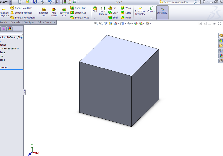
Here is a simplified step-by-step guide to creating a basic cube model using SolidWorks for novices: To begin creating your first cube in SolidWorks, start by launching the software and selecting "New" from the toolbar. Click on "Part" in the dropdown menu, as you are about to create a part that consists solely of one component. Selecting this option is essential since parts encompass a single assembly. The default setting is "Metric," but you can change it to imperial units by checking off "Imperial" and selecting your preferred unit system. Choose any value from the dropdown menu next to 'System', and make sure "Metric/ Imperial" box has a tick next to it, for better control and compatibility when collaborating or referencing different project parts later. Choose your design format; most beginners prefer "Part." Select a new part, click on a default template for metric unit measurement, pick the correct part style you wish to utilize for future edits, adjust the precision in units appropriately if desired and check that 'mm' is the preferred choice by placing a tick box alongside this metric/ imperial measurement setting which solidifies everything. On the task bar click the 'new folder icon.' Name your cube folder with an understandable file naming structure. In general terms, the file name contains a descriptive prefix of what your product's main functionality or characteristic includes as in most modern engineering work these can also incorporate additional detailed subcategories of specific parameters for referencing clarity purposes later during review meetings where different teams from various departments may request access for reviewing documentation so click OK once ready.
With this file you will be able to print Cube design with your 3D printer. Click on the button and save the file on your computer to work, edit or customize your design. You can also find more 3D designs for printers on Cube design.