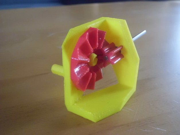
crown gears in gearcutting process
thingiverse
This is an example to make any gears by a gearcutting process. I've worked in the idea of parkinbot. Crown gears are not a kind of bevel gears. Small gear of crown gears can be moved along its axis, so there is no precision required. See Wikipedia if you need more information. Very often it is used as cheap gears in toys. Crown gear is made on punched thin sheetmetal. This shape cannot be copied to FDM printing. Printed thing: It is printed on the print?.stl files. I have made the holder as a quick and dirty design. Small gear is too small for printed plastic pins, I have used a 3mm steel rod of a linear slider of an old CD drive. Maybe this gears can be used for educational purposes. I don't see another practical use. Stl files: Most problems are the work style of OpenSCAD. It generates the cutting tool 100 times and separately all its vertices to memory. Then it makes a calculation process to find out the final shape of the object. This results in a very long rendering time because of nested for() loops. Most time I've got in my trials is >1 hour at a 100teeth gear. The mathematical system is very simple. Most work is needed to find out the computational limits and workarounds. Load crown.scad, uncomment gear1(). Render [F6] and generate .stl files. Uncomment crown_gear(). Render [F6] and generate .stl files. Load print.scad Select module you want to render and generate .stl files. I have made this 2-step process because it would be hard to design the holder when the crown gear needs to be rendered every time. Also, I have found out that creating the crown gear needs a simple hull cylinder. Inserting spokes and hubs will need more computational power and patience of programmer. It's better to do this at a second process. (I'm happy to get this solution, even it was a hard process with repairs of non-manifold stl's) I have tested to make high tooth count. This is not perfect for educational use. Characteristics of the crown gear system can be seen better at smaller tooth count. Also, I have tested to make hypoid and bevel gears in the crown cutting process. Hypoid gears normally require a twisted small gear, this will have a lot more vertices and data. So I have used a linear small gear, it will have more compromises. Bevel crown gear needs some bugfixes. Because I'm working on another idea to cut real bevel gears, I have not finished the work at bevel crown gears. (It would be a combination of a small spur gear and a crown gear in a matching angle 90deg). You will see the result if you'll change the parameters in scad file. A basic idea in my work on a gear library is the origin point [x,y,z]=[0,0,0]. Axis of the gears will match in the origin point of coordinate system. Position of the thick_end of gears is not needed to make teethcutting process. Gears can be moved easily by translate() and rotate() commands to every point you need. Another idea: It is possible to make gears with irregular teeth if you change the tool gear (linear_extrude command) to import of your own gear stl file. Feel free to play with. Gears.scad is a copy of parkinbot's Gear cutting. I have made a change to smoothen the foot of teeth. This will reduce data by 5%. https://youtu.be/qEten7H_u-A
With this file you will be able to print crown gears in gearcutting process with your 3D printer. Click on the button and save the file on your computer to work, edit or customize your design. You can also find more 3D designs for printers on crown gears in gearcutting process.
