CR-30 Belt Guides with Tracking Switches
prusaprinters
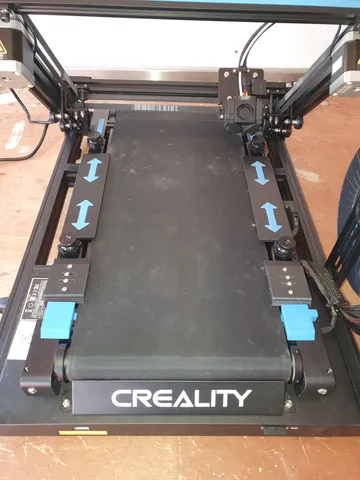
Note :- The Right and Left guides, and Right and Left Caps have been updated. Files ending V1 are updated files.These guides were created to stop the edges of the CR-30 conveyor from curling at the edges mainly when cold, and also to ensure that the printer stops should the belt tracking go out of alignment.All parts and information have been uploaded to the best of my ability, and the following information is for guidance only. (If you see any issues please let me know and i will correct) The Belt Guides can be mounted with M5 x 8.0mm domed screws and T Nuts.Switches mounted to the plates using M3 x 8.0mm domed screws.Pilot holes only for switch mounts. You can choose to put inserts in or use screws direct into plastic, just drill to your requirements.Adjust the height to allow 2 sheets of paper to fit between belt and Guide.Cable ManagmentTo contain the cables for the switches two top covers were made, these will need printing along with the Extrusion clip on cover.Step 1 Two switches will need to be connected in series to the normally closed contacts of the limit switches. Note the cables need to be soldered on the inside of the connection of the switch and pointing downwards. Route the cables via the front extrusion Top side just under the conveyor belt to reach the right hand side, as can be seen in the pictures. Do the left hand switch only at this point.Step 2 Cut the printed extrusion cover to a length of 335mm and fit the extrusion cover from the left hand side ensuring the cables are enclosed and central to either side. Pushing down on the conveyor belt will press the cover on securly.Step 3 Press on the left hand Top Cover.Step 4 Route the cables to the right hand switch position, and cut to length. Remove the wires and solder onto the right hand switch and re-mount the switch plate.Step 5 Pass the two wires ends through the right hand cap as shown in the pictures and press the cap in place ensureing all cables are retained in the extrusion.Step 6 Route the two wires into the control box via the existing cable route, see pictures.Connecting to Printer motherboardStep 1 Remove the bottom panel off the printer, and make a note where the fan is plugged into marked FAN 1. Locate the plug which should be marked TB (Thermister Bed). There are 2 wires on this plug. Cut one wire about 50mm from the plug, see picture.Step 2 Connect one of the cut wires to one of the newly installed switch wires. (I would recommend soldering and covering with Heat shrink) and connect the remaining cut wire to the remaining newly installed switch wire.Step 3 Use cable ties to tidy up all the wiring, re connect the fan to FAN 1 and fit the panel cover back on with the origonal screws.Final NotesThe 20x20 CAP-CR30.gcode file for the front extrusion cap as been zipped. Please Unzip and Use this file ONLY with a CR30 Belt Printer.Microswitch Specifications:Voltage / Current: AC 250V / 5AContact Type: SPDT - 1NO 1NC 1COMAction Type: MomentaryActuator Type: Hinge Roller LeverTerminal Type: 3 PolesOverall Size (Pole not included): 20 x 6 x 10mm / 0.8" x 0.2" x 0.4" (L*W*H)Hinge Roller Lever Length: 18mmRoller Diameter : 4.5mm/0.2"Mounting Hole Dia.: 2mmMounting Hole Spacing:10mmMaterial: Plastic, MetalThe above is the best way i can describe how to accomplish the installation should you wish to try it. Not recommended for beginners.After install at any time when the belt limit switches are activated the printer will stop and Bed and Extruder heating will be dissabled and will cool down. Motors will still be active and hold in position.I cannot change the firmware yet, and this seems a resonable way to acomplish the end result for now. I will update at a later date when i delve into the board and firmware to see if there are any pins i can use to detect the belt switches and initiate a proper shutdown with message on screen.At least now i have one less thing to worry about when printing a long duration file.Happy Printing
With this file you will be able to print CR-30 Belt Guides with Tracking Switches with your 3D printer. Click on the button and save the file on your computer to work, edit or customize your design. You can also find more 3D designs for printers on CR-30 Belt Guides with Tracking Switches.
