
Core IDX
thingiverse
10-18-23 Update: The size of many of my STLs are huge for several reasons. Some were imported as STLs and converted to solids as I modified them for my needs. Others I have manipulated too much over time. Many I can do nothing about, they are big and will remain that way, but I've reduced the STL file size of 6 STLs. By doing so, I can now get more of the STLs to show up in 3D view on this site. The updated files have 10-18-23 dates and are renamed with "-remake" or "-k". 10-10-23 Update: Two items - Assembly Hints and Images added as a new section, and an updated BOM. The new BOM has a couple of corrections/additions with supplier links. Links are like fresh fruit. They are good for a while, but as time goes by, they may may not be good. Many of the links provided I've used, but some hardware was purchased in 2019 and those links are stale. I looked around and think I've found suitable options but please purchase from your favorite trusted sources. Most links head to ZYLtech, some go to eBay, Amazon, and AliExpress. I've gotten parts from all. When ordering from ZYLtech please use code **Gilly3D5OFF**, which helps me and will reduce your purchase pricing. Here is the link to the [Core IDX BOM w/supplier links](https://docs.google.com/spreadsheets/d/e/2PACX-1vQjTBuzaijddLINa9kDuJCqbj0Fr4bNOf6u5fL6WEqT4S_oPgisqIxP4FOU-sHBz61nPyRKTvHhN-hm/pubhtml?gid=1958836868&single=true) #Core IDX ####**An IDEX Printer based on the CoreXY Design** Presented here is an advance **Independent Dual Extruder (IDEX)** linear rail system based on a **Hypercube Evolution (HEVO)** CoreXY Frame kit. It started life as a CoreXY printer and has kepts many of those attributes. While this design is HEVO specific, the concept could be applied to just about any CoreXY printer for a conversion to IDEX format. The **Core IDX** is very much like a CoreXY machine in form and function but it is an IDEX printer with two independent carriages on a single gantry that is capable of all IDEX modes. The Core IDX can do: >**Two filament prints** - could be different colors, temps and/or filament types **Duplicate Prints** - two identical parts at the same time, doubling throughput. **Mirror Prints** - two mirrored parts at the same time, again doubling throughput **Standard single filament prints** - by X or U individually [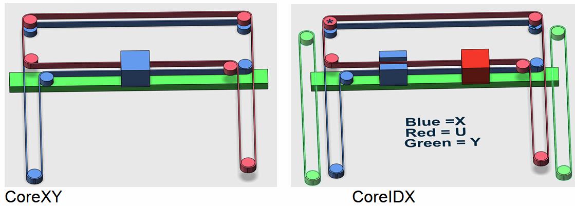](https://postimg.cc/hzfZQd8h) The drawings of the simple CoreXY and Core IDX gantries have their motors removed for simplicity and show the similarity between the two. On the CoreXY, both belts attach to the single carriage (blue). The Core IDX has two carriages, each attached to just one of the two existing belts allowing the other to bypass it. A Y drive is also added because the Gantry (green) is now independent of the original two drive motors (kind of, more on that later). This Core IDX makes use of the advantages of a CoreXY design with the only penalties being the added mass of the carriage (U) to the gantry and the Y drive gantry belt attachments at each end. Since the Core IDX printer started life as a CoreXY machine, it made sense to utilize as much of the CoreXY design as possible in the conversion. [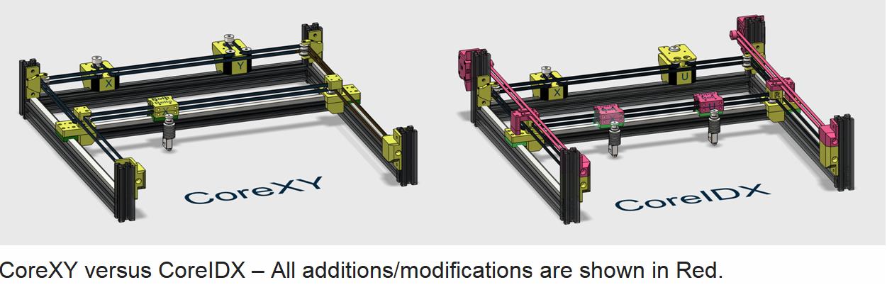](https://postimg.cc/QVWdKmBq) Very little was modified or added to make this conversion as shown in red on the CAD image comparison of CoreXY and Core IDX. This configuration has been a fully functioning IDEX system for over three years so far, although the Y Drive and Carriages have evolved multiple times. The layout of CoreXY printer belts allows for a very low gantry and carriage mass which is one of the reasons why it is so popular. When the two belts are adjusted properly, they hold the gantry in tension and perpendicular to the frame sides. It remains that way as it is moved forward and backward inside that printer frame. This attribute means less hardware and mass are needed to maintain its perfect alignment. Lower mass allows faster movement which implies faster printing while minimizing print artifacts like ringing, overshoot as well as wear and tear on the system components. This fact remains true for the Core IDX even though the two belts are attached individually to two separate carriage mounts rather than only one. The new Y drive added with two steppers and belts provides additional constraints on the alignment of the gantry. Beyond the conversion to IDEX, this printer was also optimized for ABS production. An enclosure was needed to hold the heat and to keep all the kinematic drive steppers outside in cooler air. This presentation describes the design behind the Core IDX printer and presents the Frame, Triple Z Drive, Gantry and the latest version of Carriages that use the LGX or HGX gear set. Included is a copy of my RepRap Firmware files to get this system operational and a BOM. ####**FRAME** [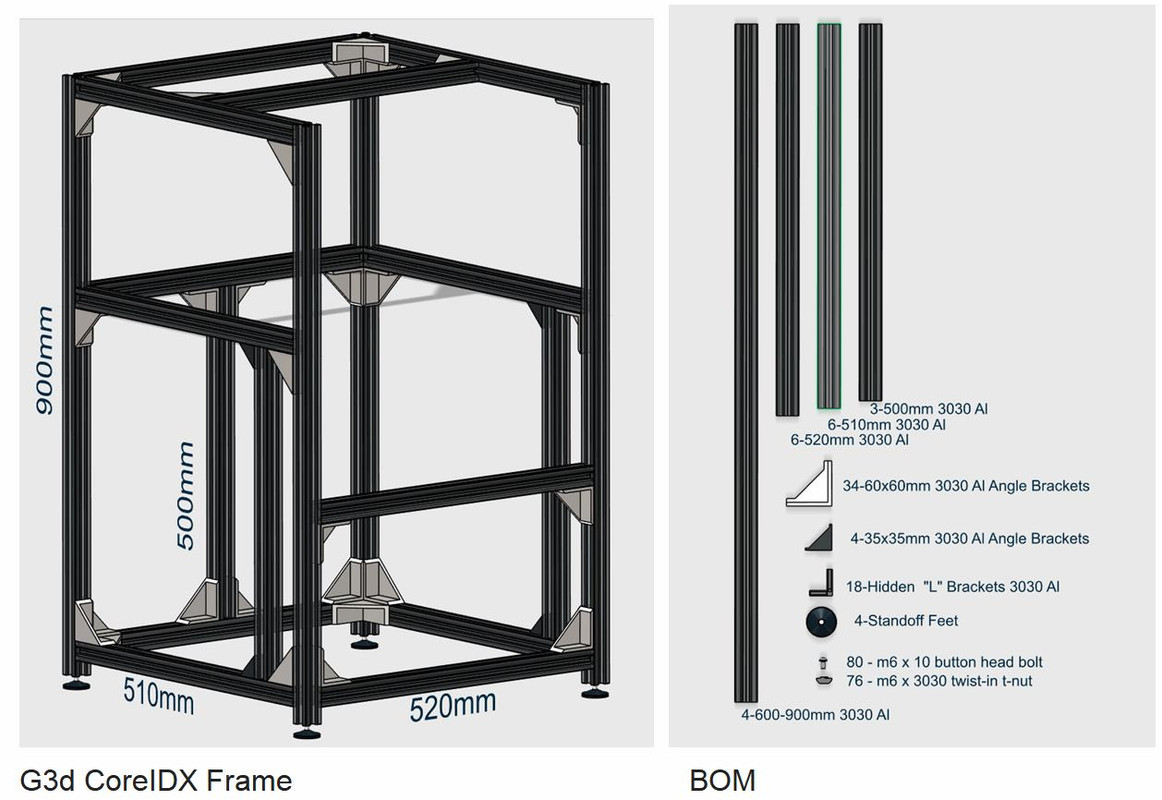](https://postimg.cc/Cny7M7tK) A HEVO Frame kit was used to build this system made up of 3030 Al extrusions. The outside dimensions are 580x570x900mm. The 900mm extrusions used for the vertical corner rails create a large enclosure above the gantry that can be enclosed to hold heat. These vertical extrusions can be shortened if an enclosure is not required, or longer linear rails and rails support could be substituted for increased Z build height. The frame utilizes corner brackets or braces at every intersection, even the bottom perimeter. The only set requirements on 3030 braces are that hidden corner “L” brackets must be used on the upper sides of the gantry frame supports (6) so the gantry rails and hardware will fit. These “L” brackets are also placed in all corners in the Frame image that do NOT show corner angle braces, includes eight under the bottom perimeter. Shown are mostly 60x60mm Angle Brackets. These are handy since they can be used as spacers to set the placement of the two front Z rail vertical support extrusions (500mm) as they need to be placed exactly 60mm behind the two front vertical Frame Al extrusions (900mm). All the other braces can be of your choice. The rear vertical Z rail support extrusion (500mm) is centered on the back frame rails, equal distance between the two rear corners. ####**Z Drive** [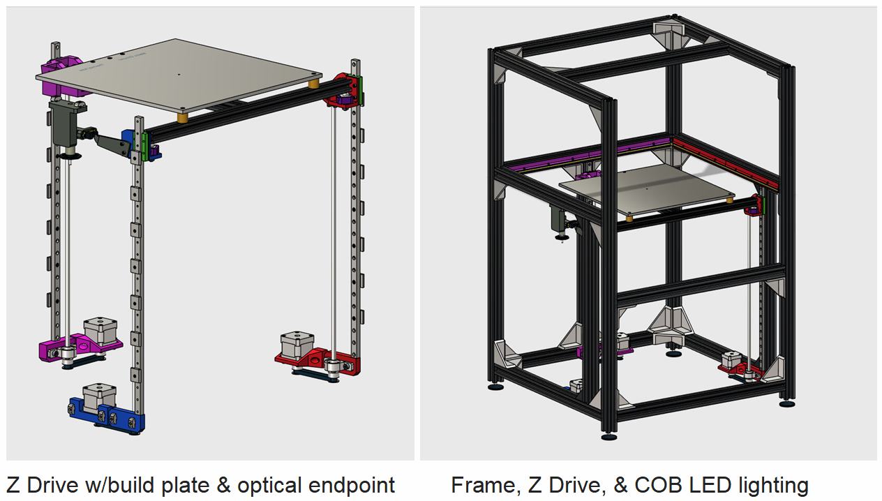](https://postimg.cc/QKs7nywc) [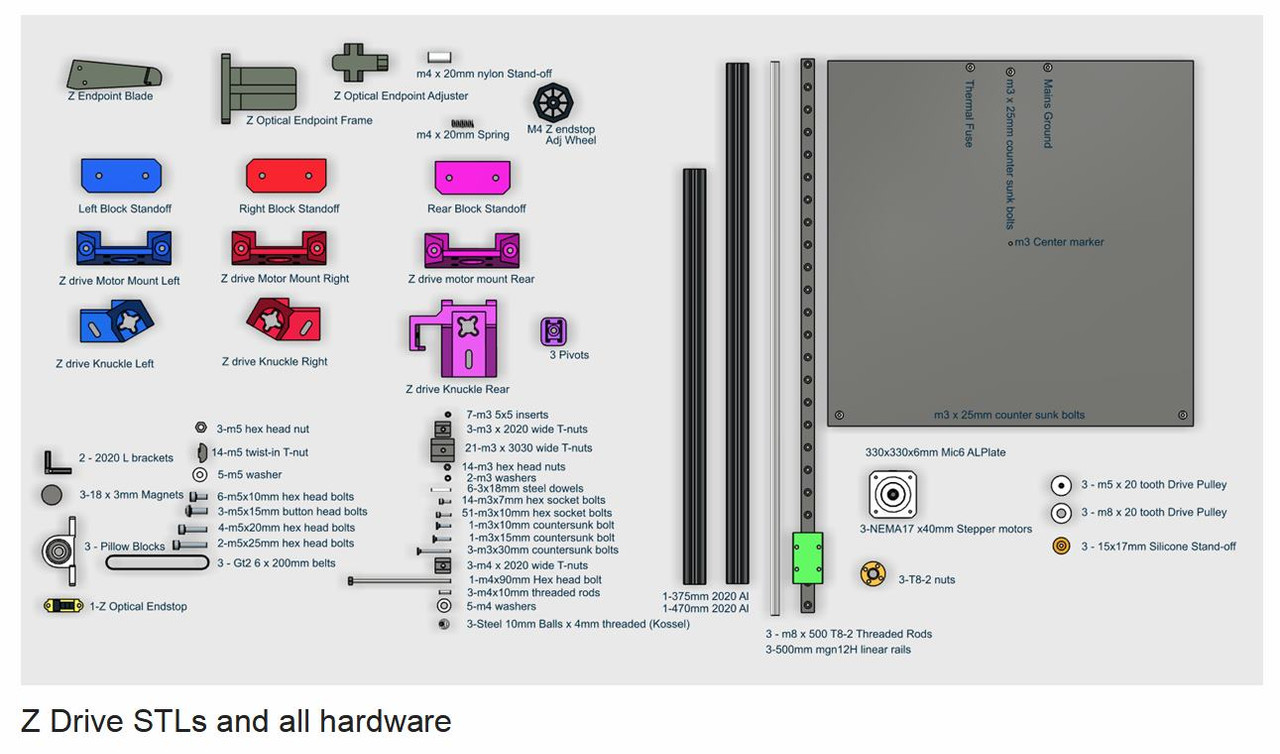](https://postimg.cc/94YwwprM) The Z drive uses three 500mm mgn12 linear rails along with three 500mm T8-2 threaded rods to make a Z build area height of just over 400mm. The T8-2 threaded rods (single thread start) used provide a 4:1 ratio increase over T8-8 threaded rods (four thread start) and provides more than enough resistance to prevent any build plate sag when the steppers are off so larger pulleys for the threaded rods are not required. If you prefer to use T8-8 threaded rods there is room for 60 tooth pulleys (3:1 ratio) but larger belts would also be needed. The pillow blocks holding the threaded rods have spacer blocks that are independent from the stepper motor mounts. The short 200mm belts are tightened by sliding the stepper motors away from the spacer blocks. Fulcrum or Pivot points are mounted on top of the three knuckles that are my version of the SolidCore triple Z pivot design by **Shane Hooper (thing:4307266)** only done in plastic. ####**Gantry System** [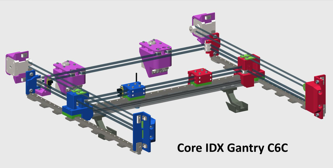](https://postimg.cc/nMCMnZYM) The HEVO frame I use has internal XY dimensions of 520 x 510mm. Three 500mm mgn12 linear rails make up a majority of the gantry hardware. Two with single mgn12H blocks are mounted on top of the two side frame rails used for gantry support and they provide for the Y movement of the gantry. Another 500mm rail with two mgn12H blocks cross the frame forming an “H” and is mounted to a 500mm 2020 AL excursion. The left and right XY Joiners connect this rail gantry system together. Also included in this gantry system are all the kinematic stepper motors, X, Y, & U endstops, and all pulley mounts. [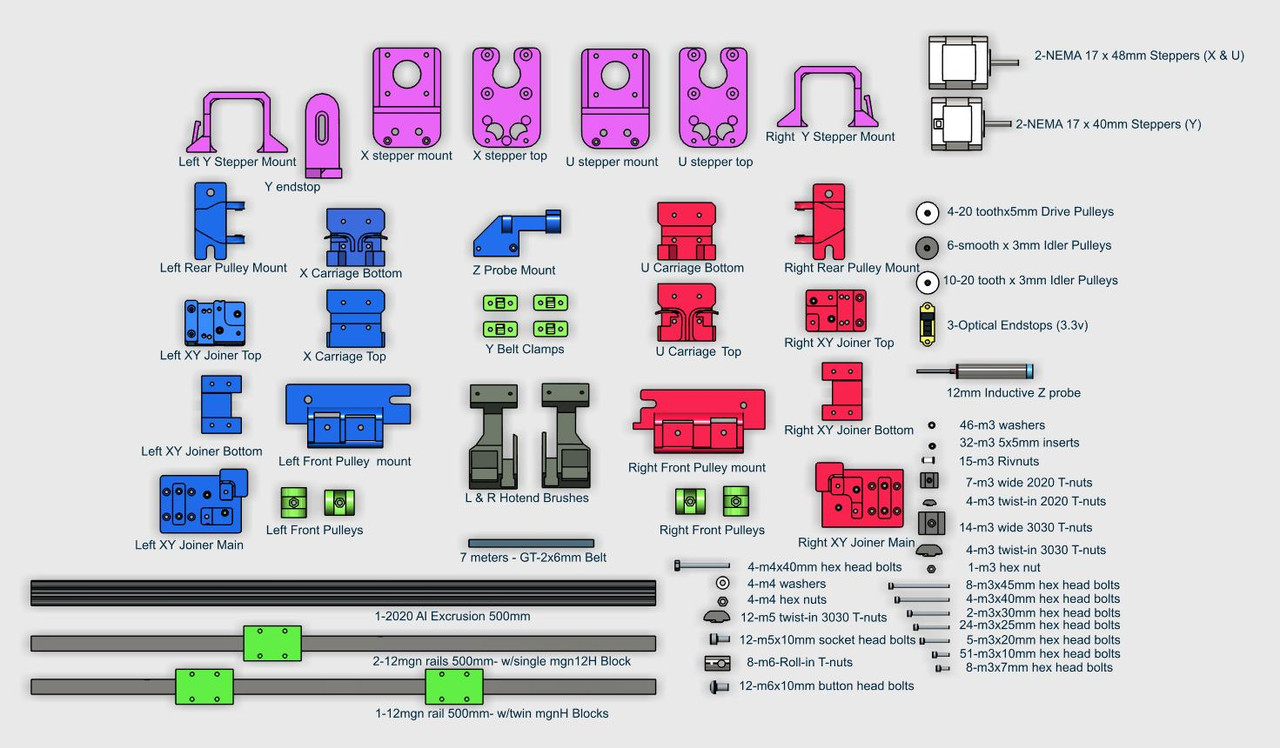](https://postimg.cc/dDrP2xJ4) When I started this project back in 2019 multiple CoreXY designs on Thingiverse and elsewhere were studied and partially built. I chose for the gantry XY joiners and rear pulley mounts a remix of **Stefan Schueller’s HEVO Fusion design (thing:2839395)**. I used a smaller linear rail size for the gantry with an added 2020 Al support extrusion, plus the whole assembly was inverted placing the belts above the gantry rail. The belts are fine tuned with adjustable pulleys located conveniently in front, similar to the **BLV** design. Those adjusters are recessed to prevent unauthorized manipulation and the tension of the belts is tuned using a nozzle wrench. The two original CoreXY stepper motor mounts (now X & U) are directly from **Kuhnikuehnast (thing:2975496)** but they also are mounted upside down. I like them because they can be placed anywhere along the back frame gantry cross member and moved later if necessary. They also meet the requirement of being mounted outside the cabinet enclosure to allow for better cooling. Brush wipers are added onto the gantry on both sides of the build plate. These brass brushes clean the tool nozzles each time they are called and retired. When doing a “two filament” print, the last thing you want are dribbles during an exchange from one of the hotends. The brush wipers eliminate the need for ooze shields, purge towers and waste chutes thereby saving both the time and filament that those solutions throw away. (https://www.youtube.com/watch?v=JW6WRsR3cCs) The downside of the wipers when added to the gantry is that the build plate width must be reduced to accommodate them. The Core IDX uses a 330 x 330 x 6mm Aluminum Mic6 build plate but the various modes of IDEX printing will have different print areas that are slightly reduced. The area for a single color print, if done by the X extruder is 300x330mm. If done by the U hotend the area is 310x330mm. If the print requires both hotends for a “two filament” print the maximum print area is 280x330mm. In duplicate mode (printing two identical prints side by side), the build plate area is split in half with each area being 165x330mm. In mirror mode it is limited to 140x330mm so that the extruders do not crash together. ####**X & U Carriages** [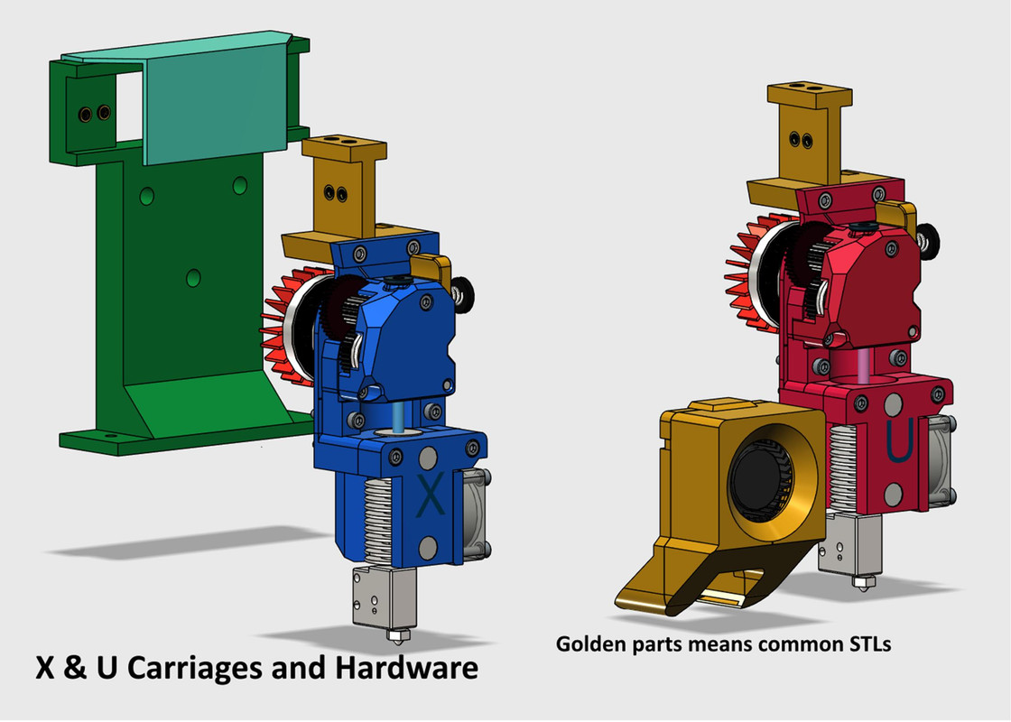](https://postimg.cc/xXcSzT8b) [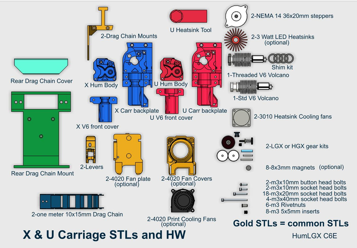](https://postimg.cc/CdST44d0) There have been multiple generations of carriages attached to this machine. The current carriages are direct drives that use the LGX or HGX (large) type of gearset and E3D V6 style heatsinks with Volcano heater blocks. The X carriage has a standard V6 heatsink mount and its Z height is fixed. The U carriage carries a 12mm threaded E3D V6 heatsink. The vertical (Z) alignment of the U hotend is adjusted by stacking shims. Both V6 heat sinks are cooled by side mounted 3010 fans. Magnets are used to attach the “print cooling” fans, if and when they are needed. NEMA 14 x 20mm stepper motors are used to drive the extruders with 3 watt heatsinks attached (optional but they look good). This design is based on the Hummingbird extruder by **nhchiu (Printables/367706)** but again modified to suit my needs. The wiring going to each carriage is carried by a 10x15 Open Outside drag chain allowing a horizontal plane of movement in X and Y that covers the entire range of carriage movement. The way the drag chains are mounted allows for the top of the machine to be fully enclosed. Sounds great? There may be a caveat. The conversion process changed the kinematic drive to something that is neither Cartesian nor CoreXY. A firmware was needed that could accomplish this new style. The Core IDX has run for several years on a Duet3D motherboard and **RepRap Firmware (RRF)**. They work extremely well and are easy to configure. Back in 2019, on the Duet3D forum, **“Haggan90”** started a thread requesting a unique kinematic formula for his new IDEX printer called **"Haq XY"** . That style is also known as **“Dual MarkForged”** kinematics. Luckily I found his thread and that solution. RRF delivers with the M669 command. Using that command you *“can specify the kinematics equations for any printer with up to 10 axes for which the movement of each axis is a linear combination of the movements of the individual motors” 1*. This command is placed in the config file and defines the unique kinematic solution for this machine. The specific command used by the Core IDX is: **M669 X1:0:0:0 Y-1:1:0:1 Z0:0:1:0 U0:0:0:1 , Core IDX kinematics** Simply put, on the Core IDX system the X, Z and U axis drives are Cartesian and act one to one, stepper movement to linear movement, but the Y drive is different. If a Y movement is requested and the X and U carriages are to move only in the Y direction thereby holding their relative X positions, both the X and U stepper motors must react either equally(U) or the opposite(X). If only the Y stepper is driven then the two carriages move in opposite diagonal paths, either together or apart depending on the Y direction moved. This Y requirement is akin to how the CoreXY kinematics works. Only RRF supports the M669 command. Included are my latest RRF files that drive my specific Core IDX machine. I recently learned that **Klipper** using the **“hybrid-corexy”** can also provide the same required IDEX kinematic solution but I have not personally confirmed it. I believe **Marlin** may be working on this but I do not know the progress. To use RRF, a Duet3d style motherboard is required, or at least one capable of RRF. I use a Duet 2 WiFi v1.04 mother board and added external stepper driver boards. Other motherboards that can run RRF include many 32 bit LPC or STM32 motherboards including many of the 32 bit boards labeled MKS, SKR, and Fly, but not all. The ability to drive nine steppers is also a requirement. Eight drivers can be used if the motherboard has a driver with a dual plug output. By redefining that stepper driver circuit that the Duet MB normally uses for a dual Z Drive (two stepper plugs in series) as my Y drive, both Y stepper motors can be hooked to that driver. If this is done then one of the two Y stepper motors must be plugged in backwards so that they turn in opposite directions. There are five drivers located on the Duet 2 WIFI motherboard and they are used for the X, Y, U, E0, E1 drives. Three separate external driver cards are used for the Z Drive allowing each to be adjusted separately for bed leveling. Build instructions are “in the works” but not completed. Everything has been tested and run extensively. Meanwhile additional photos and CAD images can be provided to help with assembly if requested. In addition, Zyltech will soon be providing links for the hardware they can provide. When that is available, the BOM will be updated to include that and additional links to where the other hardware can be found. 1) Quote from: (https://reprap.org/wiki/G-code#M669:_Set_kinematics_type_and_kinematics_parameters)
With this file you will be able to print Core IDX with your 3D printer. Click on the button and save the file on your computer to work, edit or customize your design. You can also find more 3D designs for printers on Core IDX.