Constant Velocity Joint LCD-Knob
prusaprinters
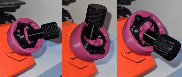
Object description:This LCD knob can be rotated in a wide range of angles from all sides.A video how it works you can find here: CV Joint Knob Video. But please note, that the fit of the main part on the LCD was a bit wobbly with this prototype. It's corrected in the download-model.I know, this LCD knob is completely over-engineered and basically totally nonsense. But it was fun to design it and bring it to work for the LCD knobs contest.Triggered by verny's Cardan Joint Knob I thought I could bring the crazyness to a even higher level.May some people know that a cardan joint has a big disadvantage. The driven part rotates during one turn two times too fast and two times too slow. The higher the angle, the bigger becomes this effect.Using a constant velocity joint guarantees always the same output rotation speed, independend of the bending angle.In principle it is like a ball bearing, but much more complicated in detail because it has to transmitt rotational torque under every possible angle. Comments:I printed all the parts with a 0,25mm nozzle. A 0,4m nozzle should also work.Especially when parts were printed with a 0,4mm nozzle, I recommend to sand the sphere surfaces slightly for a smoother function.If you want a really smooth funtion, you can put a bit of grease on the contact surfaces.If you have six metal balls with diameter 8mm available, you can use it instead of the printed balls. They will of course roll much more better than the printed ones.Fine tuning:If you want to reduce the radial play, you can scale the balls and the connector slightly up.If balls fits too tight in the tracks, you can scale the balls and the connector slightly down.Number of pieced needed:Each one of outer race, inner race, cage and knob6x connector12x ball_half Assembly instruction (looks more complicated as it is):Assembly of inner race and cage:The cage has a smaller front diameter ( = the print bed surface) and a bigger front diameter. Lay it down on the smaller one as it was printed, with a cage window showing to you.Now take the inner race. Please note that it has on the top side with the connecting hole two bigger chamfers. Turn the inner race axis 90 degrees to the cage axis. Stick the contout with the one bigger chamfer into a cage window and rotate the whole inner race into the cage.Once the inner race is completely inside the cage, rotate it 90 degrees back with the connection hole to the front that both axis are aligned.Assembly of inner race with cage into the outer race:Rotate the preassembled cage 90 degrees to the outer race.Align the cage windows with the inner sphere of the outer race and push the cage in.Now you can turn the cage 90 degrees back until all axis are aligned.Assembly of balls:First of all, assemble the two halfs of the balls with the connector. You can glue it together, but if the parts stick good together it is not necessary.Align the tracks of the inner race and the outer race.Bend the inner race and the cage until it is enough space to put in one ball through the cage window into the open tracks.Repeat it 6 times until all balls are assembled.Assembly of the knob:Simply push it into the hole of the inner race.Once assembled, the joint can't be disassembled as long as the knob stucks inside the inner race. Print settings:Material: PLA, PETGLayer height: 0,15mm or smallerInfill: 15%Perimeters: 2Brim: no, maybe for the small ball-halfs and the connectors. It depends mainly on your bed adhesion.Support: only for the cage (aready included in the 3mf-file)
With this file you will be able to print Constant Velocity Joint LCD-Knob with your 3D printer. Click on the button and save the file on your computer to work, edit or customize your design. You can also find more 3D designs for printers on Constant Velocity Joint LCD-Knob.