Conformal Robot Gripper
prusaprinters
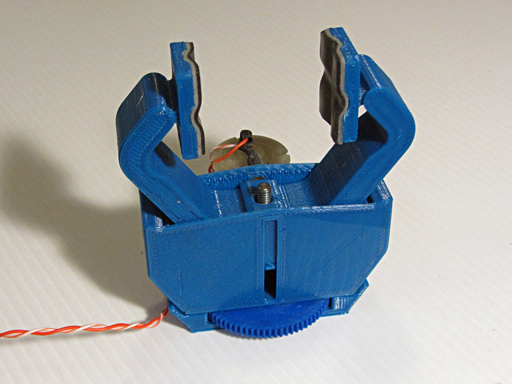
<p>This compact gripper has pivoting fingertips that conform to the object being gripped. Unlike parallelogram grippers, this provides a more secure grasp on irregular surfaces. And rather than using fixed pivots, each finger is actually a rolling gear trapped between two racks. This helps keep the low profile as the fingers open and close.</p> <p>UPDATE: I've also posted a STEP format CAD file for this gripper</p> <h3>Print Settings</h3> <p><strong>Printer Brand:</strong></p> <p>MakerGear</p> <p class="detail-setting printer"><strong>Printer: </strong> <div><p>MakerGear M2</p></div> <p><strong>Supports:</strong></p> <p>Yes</p> <p class="detail-setting resolution"><strong>Resolution: </strong> <div><p>0.2mm</p></div> <p><strong>Infill:</strong></p> <p>20%</p> <p><strong>Filament:</strong></p> Inland PLA <p><br/> <p class="detail-setting notes"><strong>Notes: </strong></p> </p><div><p>All parts are pretty straightforward to print, except for the gear and pinion. These have tiny 48p teeth that printed with a 0.35mm nozzle and using a 0.35mm line width. Even if you are using a 0.4mm nozzle, however, you can still get away with manually specifying a 0.35mm line width.</p> Print one of everything except you'll need 2 fingers and 2 finger tips. <p>After printing make sure you remove all of the support material from the inside of the gripper base and from the cavities at the ends of the fingers.</p> <h3>Post-Printing</h3> <p><strong>Parts Required:</strong></p> <p>DC Motor: <a href="https://www.jameco.com/z/QJT-260-18130-3VDC-Motor-4780-RPM-Solder-Terminals_1951449.html">https://www.jameco.com/z/QJT-260-18130-3VDC-Motor-4780-RPM-Solder-Terminals_1951449.html</a></p> <p>1.55" long, 8-32 threaded rod (may substitude M5 thread)</p> <p>8-32 nut (0.312" width)</p> <p>4-40 x 1/2" long flathead screws (may substitute M3 screws) - qnty 2</p> <p>4-40 x 1/4" long pan head screw (may substiture M3 screws) - qnty 2</p> <p>Adhesive backed rubber finger pads (I used thin rubber sheet adhered with thin double-sided foam tape)</p> <p><strong>Assembly:</strong></p> <ol> <li>Tap the center hole of the big gear with an 8-32 tap. Make sure the tap is held square to the gear face.</li> <li>Apply a drop of superglue to the threaded hole and thread the 8-32 rod into hub-side of the gear until the end of the rod is flush with the opposite (flat) side of the gear.</li> <li>The motor has 2 mounting holes just about the right size for 4-40 screws. Use one of the screws to form a shallow thread into the sheet metal housing. (If using M3 screws, you may need to use a tap to form the threads.)</li> <li>Remove the built-in supports in the center of the rack segment piece and insert the 8-32 nut.</li> <li>Refer to the cut-away view of the gripper. Tilt both fingers in the wide-open position so that the top tooth of the finger just engages the top tooth of the rack in the gripper base. Slide the rack segment in in-between the two finger gear segments.</li> <li>As you close the fingers, the small tabs at the bottom of the rack segment will flex the side walls of the base apart, and then ultimately click into place in the side slots in the base.</li> <li>Apply rubber or foam finger pads to the finger tips and snap them into the cavities in the ends of the fingers.</li> <li>Insert the threaded rod and gear into the bottom of the base and then thread into the nut captured in the rack segment. Apply a little light grease to the thread and to the hub of the gear where it rubs against the base.</li> <li>Use a 0.076" drill bit to clean out the hole in the pinion gear. Press this gear onto the motor shaft, hub side first, until the flat side of the gear is flush with the end of the motor shaft.</li> <li>Insert the motor boss into the bottom plate and secure with the two flathead screws.</li> <li>Place the gripper base onto the bottom plate and secure with the two pan head screws. There should be a little play in the screw holes to that you can adjust the center distance of the two gears for smooth operation. Apply a little light grease to the gear teeth.</li> <li>To mount your gripper, you will need to remove the bottom plate, screw it to your robot end flange (4 flathead screws on 0.875" dia bolt circle), and then re-attach the gripper base to the bottom plate.</li> </ol> <p><strong>Use:</strong></p> <p>To use this gripper, you will need to be able to adjust the voltage (or current) going to the motor. It is a 4.5v motor with a stall current of 1.6A. However, running the motor at the stall current form more than a few seconds can burn out the motor. The other tricky part of operating the gripper is that it is possible to have the gripper lock itself closed on an object and not be able to open back up because the static friction for opening is higher than the dynamic friction present when closing.</p> <p>I would recommend the following technique for opening and closing the gripper:</p> <p>To open, first apply 4.5v for about 1/2 second to overcome any static friction locking the gripper closed. Then apply about 3v for a 2-3 seconds to continue opening the gripper all the way until it hits the end stop. The screw drive is non-backdrivable so it will stay open with no voltage applied.</p> <p>To close, apply -3v for 2-3 seconds until it closes fully on your object. Applying more than 3v may cause to lock to object so tightly that you cannot get it to loosen again. When you turn off the voltage, the non-backdriveable screw will maintain it's grip on your object.</p> <p>Note that the exposed part of the big gear makes a handy thumbwheel for manually adjusting the gripper open or closed.</p> </div></p></p> Category: Robotics
With this file you will be able to print Conformal Robot Gripper with your 3D printer. Click on the button and save the file on your computer to work, edit or customize your design. You can also find more 3D designs for printers on Conformal Robot Gripper.