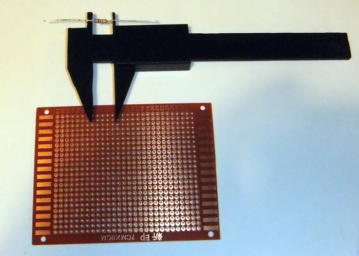
Component Lead Bender Caliper
pinshape
This tool draws inspiration from a gadget featured in an old 1960s electronic hobbyist magazine I came across recently. Component lead bending tools are not new to this community, but this variation brings precision to your bends. To use it effectively, position the caliper's points into the two holes where you plan to install your component, place the part in the middle of the gap on top, and bend the leads around the edges. For added precision, you can install a screw into the hole on top of the slide. Then, tighten down the slide so it won't move while you bend your leads. Guesswork is eliminated when determining how far apart to bend the legs of resistors or other axial leaded discrete components. Printing the tool in the same orientation as the .slts files - with the slide standing upright and the pointer at the bottom, and the main body flat on its side so that the component's gap faces the build plate - yields optimal results.
With this file you will be able to print Component Lead Bender Caliper with your 3D printer. Click on the button and save the file on your computer to work, edit or customize your design. You can also find more 3D designs for printers on Component Lead Bender Caliper.
