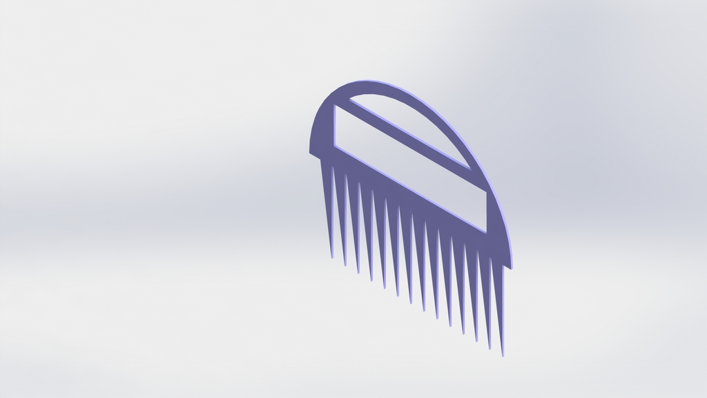
comb
thingiverse
Designing a Comb with SolidWorks CAD Software To create a functional comb using SolidWorks computer-aided design (CAD) software, one must start by launching the program and navigating to the "File" menu to select "New." From there, choose "Part" under the "SolidWorks" tab to begin designing the comb's body. The first step involves sketching out a 2D representation of the comb's shape using various lines and curves. This can be done by selecting the "Sketch" tool from the toolbar and choosing the desired line style. For instance, a series of straight lines can be used to create the comb's teeth, while curved lines can define the handle. Once the sketch is complete, it's time to extrude the design into a 3D model. This is achieved by selecting the "Extruded Boss/Base" feature from the "Features" tab and specifying the desired height for the comb's body. Next, add material properties to the part by going to the "Properties" panel and entering the required values under the "Materials" section. Choose a suitable material that suits the intended use of the comb, such as plastic or metal. After defining the material properties, proceed to create a 2D drawing of the comb's design by selecting the "Drawings" tab in the top menu bar. This will allow for further modifications and adjustments to be made on the design before sending it off for manufacturing. Finally, export the SolidWorks file as an STL format to be used with 3D printing software or other computer-aided manufacturing (CAM) tools. With these steps, one can successfully design a functional comb using SolidWorks CAD software.
With this file you will be able to print comb with your 3D printer. Click on the button and save the file on your computer to work, edit or customize your design. You can also find more 3D designs for printers on comb.
