CNC frame rock tumbler
thingiverse
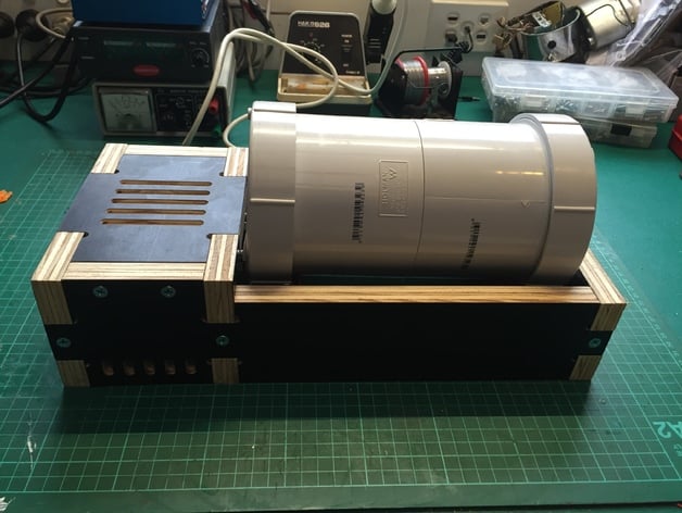
Heavy-duty Rock Tumbler / Barrel Rumbler Polish Rocks or Metal 3D Printed Parts! This Design Uses a Mains-Powered AC Synchronous Geared Motor, Which Runs Quietly and Reliably for Long Durations. The Barrel Is Made from Cheap, Durable PVC Plumbing Components and Can Be Optionally Lined with Rubber or a Printed Insert. Mine Is Lined with Checkerplate Rubber Sheet. Note That I Am in Australia. Barrel Parts Are Available from Bunnings 'Holman' Brand. Electrical Parts from Jaycar. The Motor and Rubber Mounts Are from eBay, and the O-Rings Came from a Kit from Aldi. Bill of Materials Frame: 6 Parts, CNC Cut from 18mm Plywood Cover Plate, from Thin Acrylic / Aluminium Etc (I Used 2mm Clear Acrylic) 10 x 10G x 30mm Wood Screws 4 x Small Self-Tapping Screws Approx 3mm x 10mm Long for Cover Plate Printed Parts: 4 x Drive Wheels 1 x Motor Pulley 2 x Shaft Pulleys Plug to Cover Motor Shaft Hole (STL Is Included with All Parts for Printing) Hardware - Barrel: 2 x 100mm PVC Threaded Access Coupling (105mm Long Overall) 2 x 100mm PVC Screw on Cap Short Length of 100mm PVC Pipe PVC Glue / Primer Hardware - Mechanism: Motor - AC Synchronous Geared 100RPM 60mm x 60mm 4 x M4 15mm x 15mm Rubber Mounts, Male - Female Threads 4 x M4 x 25mm Machine Screws 4 x M4 Nyloc Nuts and Washers 1 x M3 Grub Screw + Nut (for Motor Pulley) 2 x 300mm Lengths of M8 Threaded Rod 20 x M8 Nuts, 13mm Hex (I Used 8 x Nylocs and 12 x Plain Nuts) 4 x 608ZZ (Skateboard) Bearings 2 x O-Rings 50mm ID x 3.55mm for Drive Bands 4 x O-Rings 28mm ID x 3.55mm for Drive Wheel Hardware - Wiring: The Motor Has 3 Terminals. The Middle Terminal Is Neutral and the Outer Terminals Are Each Active, for a Different Rotation Direction. Connect the Active to Only 1 of the Outer Terminals and Leave the Other One Unconnected. If You Are Using a Metal Cover Plate, It's a Good Idea to Connect the Earth Wire to It. Otherwise, Connect Earth to the Motor Housing via One of the Mounting Screws. Fit the Rest of the Frame Plus the Cover Plate with 4 x Small Self-Tapping Screws Before Operating. Print Settings Printer Brand: RepRap Printer: Prusa i3 Rafts: No Supports: No Resolution: 0.20mm Infill: 50% Notes: Frame CNC Cut from 18mm Film-Faced 'Form Ply' Plywood Using 3.175mm and 6.0mm Tools on Chinese 6090 Router. How I Designed This This Was My Inspiration for the Barrel Design, Threaded Rod Shafts, and Drive Wheels: http://www.thingiverse.com/thing:935252 Given That I Have a CNC Router I Decided to Design It from Plywood Rather Than Printed Brackets. I Also Found a Suitable AC Geared Motor and Opted for Belt Drive Instead of Gears for Quietness, Since This Needs to Run for Weeks at a Time! This Was Designed in Solidworks Then Exported to Slic3r for 3D Printed Parts and ArtCam Express for CNC Parts.
With this file you will be able to print CNC frame rock tumbler with your 3D printer. Click on the button and save the file on your computer to work, edit or customize your design. You can also find more 3D designs for printers on CNC frame rock tumbler.