Circularity (XY calibration) test
prusaprinters
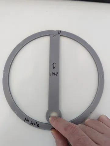
My Mk3S+ has an X/Y calibration error of about 0.1%, which is excellent for normal usage. However; because it is a systematic error, accounting for this small error can imporove the accuracy of a model, particulary for large round parts which need to rotate smoothly, e.g a shaft in a bushing, or in my case a rotating piston in a housing (think Wankel engine). The test has two parts, and external ring, and an internal rotor. These are printed separately. The rotor has a hole for a finger to lightly push it against the side of the outer ring, and the gap at the opposite side is measured. This is repeated for various directions of the rotor, e.g. North, East, South, West. The average of the North and South gap compared to the average of the East and West gaps can be used to determine the error in the X/Y calibration.The microscope images attached to this page are of the gap when the rotor is pointing North, and the slightly larger gap when the same rotor is rotated 90 degrees counter clockwise to be pointing West. These positions are demonstrated in the attached photographs. The model doesn't have a North marker on it, so remember to mark which way is North when they are printed (and any scaling if it was applied for the scaling series below). An additional way to make this test more accurate is to scale the outer ring in equivalent and opposite amount for both X and Y, and then find the amount of scaling required for 0 error. The g-code files provided are for rotors which are scaled by X: 100%, Y: 100% (no scale)X: 99.93%, Y: 100.07% (0p07 scale)X: 99.86%, Y: 100.14% (0p14 scale)X: 99.79%, Y: 100.21% (0p21 scale)and the Rotor has two lengths, rotorThick_noOffset which is about 168 mm long, and rotorThick_200micronGap which is about 169.8 mm long. The longer rotor leads to smaller gaps such that the error in XY calibration gets larger as a fraction compared with the gap size. This makes the test a bit easier to analyse. I.e. probaly best just to print rotorThick_200micronGap_11g_PLA_49m.gcode, or scale your rotor to have a small gap (this needed about X: 99.90%, Y: 100.10% for me).You can use Prusaslicer to make your own range of scales, C.f. the attached file example of 0p5pcScale.png. In doing this you need to make sure you uncheck the lock icon so you can scale X and Y independently. In my case from 2 repeats of this experiment the scaling required to achieve 0 error was 0.07% the first time and 0.09% the second time. The printer needed to get smaller in X and bigger in Y. I was able to apply this scaling to my rotating pisons and chambers (in my Wankle-like engine model) to print parts with rotation gaps slightly tighter than the piston/chamber gaps from parts which I had professionaly prepared to be round on a lathe… which for me is an amazing achievement from the printer :-) N.B. the errors in this calibration can be pretty small, of the order of 100 micron over 160 mm, I used a USB microscope and feeler guages to analzy the data. I'm not sure how useful it will be without these analysis tools. If you don't have these tools probably can increase the size of the rotor to give an interefence fit when rotating and then play around with the scaling of the outer ring to make it round…
With this file you will be able to print Circularity (XY calibration) test with your 3D printer. Click on the button and save the file on your computer to work, edit or customize your design. You can also find more 3D designs for printers on Circularity (XY calibration) test.
