Cat treadmill
prusaprinters
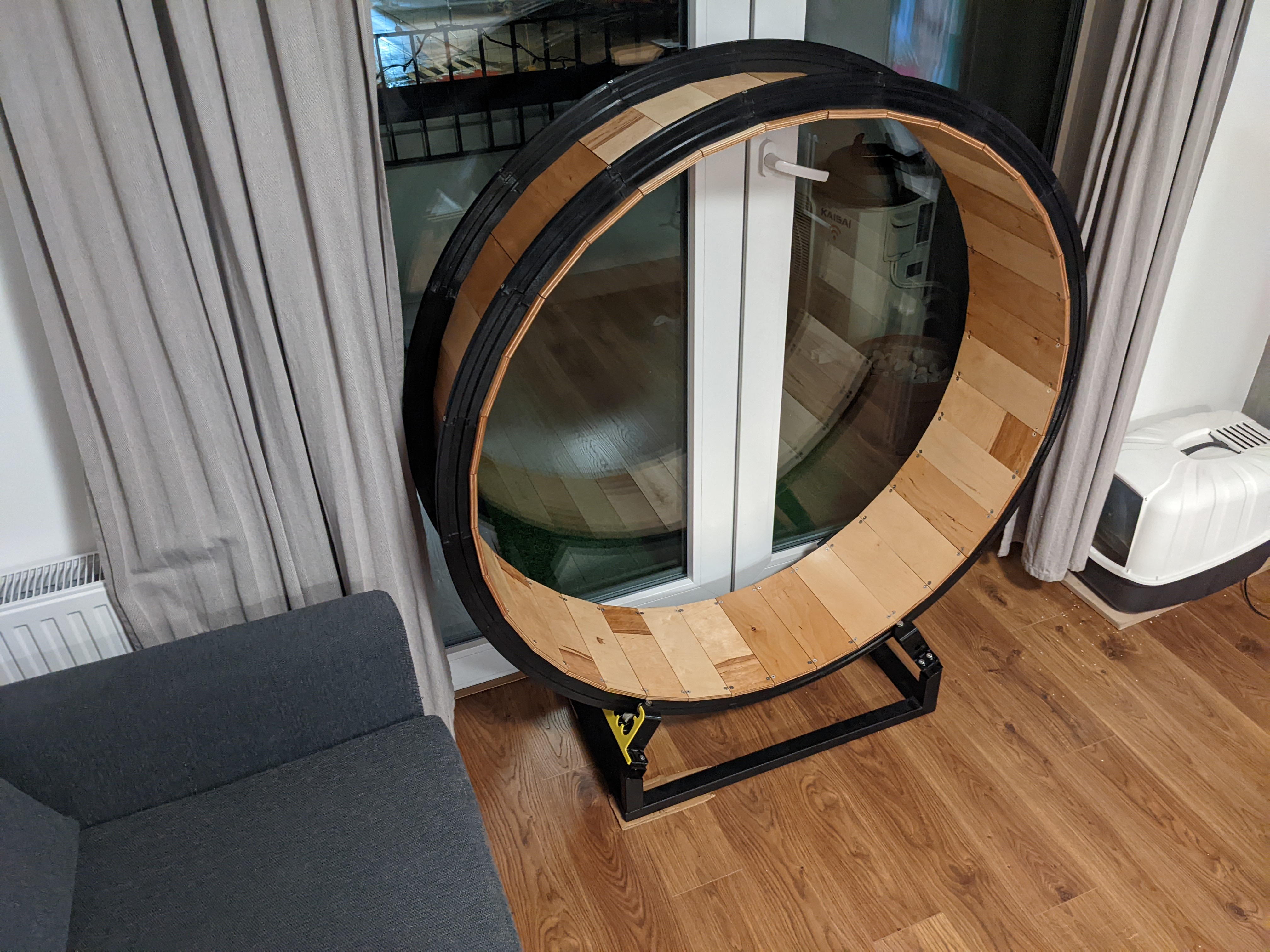
<p>This is more of a build log than direct instructions - I wanted to share design decision I made - maybe it will help someone in whatever they will design. However if you are crazy enough to build one - here you should find all the information you need, but if you will need more - I will be happy to help</p><h4>End result</h4><figure class="image image-style-align-center image_resized" style="width:50%;"><img src="https://www.notion.so/image/https%3A%2F%2Fs3-us-west-2.amazonaws.com%2Fsecure.notion-static.com%2Fd63f6407-59fc-459e-8a81-232ef69dd873%2FUntitled.png?table=block&id=e7cbcf52-584b-43e1-a222-1eaf1e881f44&spaceId=588ecd34-c38e-4947-a968-34865e1c4d27&width=1730&userId=187c2e75-274f-4405-84d2-bd7ed4440fcc&cache=v2"></figure><figure class="media"><oembed url="https://www.youtube.com/watch?v=vBmEupgXqRI"></oembed></figure><p>Cats are being slowly trained in using the treadmill, it takes time, and they’re not always doing what I would expect, but it’s a start, and I sure had fun designing and building it.</p><p>I built a treadmill for my cats.</p><p>Why? Any of the options on the market, or DIY versions were not what I wanted (different for different reasons)</p><p>How it went?</p><p>I started with a reaserch on how different people approached the build of this treadmill. I found that most of them were either tube connected in the center to the bearing or something similar to what I’ve built.</p><p>I didn’t liked the design of mounting in the center because I imagined It would be huge cantilever and would simply bend. Though I know people successfully implemented this design!</p><p>Design process</p><p>Whole thing was created in Fusion 360.</p><figure class="image image_resized" style="width:50%;"><img src="https://www.notion.so/image/https%3A%2F%2Fs3-us-west-2.amazonaws.com%2Fsecure.notion-static.com%2Fff1116fb-7daf-4a5c-8d3e-65a108c0908c%2FUntitled.png?table=block&id=71519cea-dff1-4357-ac26-a198f1cc790f&spaceId=588ecd34-c38e-4947-a968-34865e1c4d27&width=1730&userId=187c2e75-274f-4405-84d2-bd7ed4440fcc&cache=v2"></figure><p>Finished design</p><p>My idea was to create something that will consist of rails (here in black) and planks that will connect them. First problem I had to solve was how to shape a rail? I wanted to create something in a shape of I-beam. They have really good ratio of cross-section area to stiffness and strength.</p><p>Moreover since one of my cats is pretty active I wanted to minimise the risk of them toppling the wheel. Using the I-beam would allow me to put little supporting wheels on the sides so there is no way for the treadmill to fall off.</p><p>As a diameter I chose 120cm, simply seemed like good dimension based on commercially available ones.</p><p>Also - I didn’t wanted for the wheels to drive on polygon, but rather a circle - I thought that way it would be quieter.</p><h3>I-beam</h3><p>It was iterative approach - I designed what I thought was beefy enough, imported into slicer, see how heavy it would be, went back and changed dimensions.</p><figure class="image image_resized" style="width:50%;"><img src="https://www.notion.so/image/https%3A%2F%2Fs3-us-west-2.amazonaws.com%2Fsecure.notion-static.com%2F73e04f89-a52d-4fdd-ac0b-8520a64c1f58%2FUntitled.png?table=block&id=ee3eb853-69b1-49e3-b951-126a54074740&spaceId=588ecd34-c38e-4947-a968-34865e1c4d27&width=1730&userId=187c2e75-274f-4405-84d2-bd7ed4440fcc&cache=v2"></figure><p>My idea was to print them on the side - 135 deg angle means 45 deg overhang which is easy to print, and then we have 10mm bridge which is not a problem for my printer too.</p><p>In the hindsight - I think I should’ve iterated on it more and made it as light as possible. Possibly by using simulations.</p><h3>Rails as a whole</h3><p>Since my 3d printer is not big enough to fit 120cm ring on it (its bed is 210x250mm) I needed to split rails for printing and connect them afterwards. I decided on using M5 bolts and nuts.</p><figure class="image image_resized" style="width:50%;"><img src="https://www.notion.so/image/https%3A%2F%2Fs3-us-west-2.amazonaws.com%2Fsecure.notion-static.com%2Ff4c1269e-1f14-4f0b-9b49-8c850425cce6%2FUntitled.png?table=block&id=44aa1280-9bad-4dc6-8d5b-f01f0b6cec40&spaceId=588ecd34-c38e-4947-a968-34865e1c4d27&width=1730&userId=187c2e75-274f-4405-84d2-bd7ed4440fcc&cache=v2"></figure><p>One end of the part</p><figure class="image image_resized" style="width:50%;"><img src="https://www.notion.so/image/https%3A%2F%2Fs3-us-west-2.amazonaws.com%2Fsecure.notion-static.com%2F60e76828-eb4e-480f-ba28-1cfbdefa75dc%2FUntitled.png?table=block&id=a88377e4-f0f9-4f15-a3ab-5208ee7397ba&spaceId=588ecd34-c38e-4947-a968-34865e1c4d27&width=1730&userId=187c2e75-274f-4405-84d2-bd7ed4440fcc&cache=v2"></figure><p>Other end</p><p>Both of the ends were designed in a way that they should be easy to print and interlock nicely. And yeah, they worked exactly that way!</p><h3>Wheels system</h3><p>Idea was to have wheel on the rails from the bottom - so treadmill can rotate, and from the sides so it won’t fall down.</p><p>I have bought some time ago a lifetime supply of 608ZZ bearings so it was fairly easy to decide which ones I will use.</p><figure class="image image_resized" style="width:50%;"><img src="https://www.notion.so/image/https%3A%2F%2Fs3-us-west-2.amazonaws.com%2Fsecure.notion-static.com%2Fff2e4246-0479-4f05-bbd7-a611de42b19d%2FUntitled.png?table=block&id=24ec9ae4-f567-4376-a18f-3308ade6842e&spaceId=588ecd34-c38e-4947-a968-34865e1c4d27&width=1730&userId=187c2e75-274f-4405-84d2-bd7ed4440fcc&cache=v2"></figure><p>Cross section of wheels system</p><figure class="image image_resized" style="width:50%;"><img src="https://www.notion.so/image/https%3A%2F%2Fs3-us-west-2.amazonaws.com%2Fsecure.notion-static.com%2Fc9708ea4-3e47-4859-805c-4d9a98c79fe3%2FUntitled.png?table=block&id=e5075b1b-254c-4687-a505-fb44e1208a84&spaceId=588ecd34-c38e-4947-a968-34865e1c4d27&width=1730&userId=187c2e75-274f-4405-84d2-bd7ed4440fcc&cache=v2"></figure><p>Wheels assembly</p><p>Everything can be assembled using M8x50 socket cap head screws, washers and locknuts. Holes are designed to be undersized and then drilled to achieve better precision. Slots in the bottom are for bolting assembly to a frame, they are elongated so any mistakes made during building frame can be corrected.</p><p>Trickiest thing here was to correctly design distance between side wheels - first version was too tight, then I designed slot instead of a hole so it could be adjusted, but it was painstakingly hard. So instead of guessing I just measured printed rail, and set distance to that.</p><p>Wheels were printed out of soft filament (Noctuo grip soft) it’s not TPU, but I couldn’t find the name of the material itself, only the brand name. FIlament is as hard as boiled spaghetti.</p><h3>Frame</h3><p>It was designed to be welded because: welding is fun and heavy steel base will lower center of gravity and make things stable. It probably could have been done out of wood, and maybe weighted by cheap concrete pavement slabs if needed.</p><figure class="image image_resized" style="width:50%;"><img src="https://www.notion.so/image/https%3A%2F%2Fs3-us-west-2.amazonaws.com%2Fsecure.notion-static.com%2Fbc32b593-689b-4b29-8480-f42138be2f7c%2FUntitled.png?table=block&id=ef5382d6-023c-4850-ab5c-22e931618263&spaceId=588ecd34-c38e-4947-a968-34865e1c4d27&width=1730&userId=187c2e75-274f-4405-84d2-bd7ed4440fcc&cache=v2"></figure><p>FInal frame is different than the drawing, though dimensions match. Wheels assemblies are fixed to the frame using M8 bolts and rivet nuts.</p><h3>Track</h3><figure class="image image_resized" style="width:50%;"><img src="https://www.notion.so/image/https%3A%2F%2Fs3-us-west-2.amazonaws.com%2Fsecure.notion-static.com%2Ff6f9d08c-6d73-48ee-b97f-fbbba65daa5c%2FUntitled.png?table=block&id=16e9ef21-9ab9-468b-8c5c-71bcc5217d57&spaceId=588ecd34-c38e-4947-a968-34865e1c4d27&width=1730&userId=187c2e75-274f-4405-84d2-bd7ed4440fcc&cache=v2"></figure><p>I designed track to be built using 30cm wide, 9mm thick plywood, cut at 5deg angle. I needed 36 pieces. Exact width of plank and placement of mounting holes to fix it to rails was something that was driven by other dimensions, and I simply measured it afterwards.</p><figure class="image image_resized" style="width:50%;"><img src="https://www.notion.so/image/https%3A%2F%2Fs3-us-west-2.amazonaws.com%2Fsecure.notion-static.com%2F30d8ca3b-fdda-4efb-b34c-40166d03931a%2FUntitled.png?table=block&id=00ef8283-0857-4600-9995-e221c5f77861&spaceId=588ecd34-c38e-4947-a968-34865e1c4d27&width=1730&userId=187c2e75-274f-4405-84d2-bd7ed4440fcc&cache=v2"></figure><p>Final version of the rail segment</p><figure class="image image_resized" style="width:50%;"><img src="https://www.notion.so/image/https%3A%2F%2Fs3-us-west-2.amazonaws.com%2Fsecure.notion-static.com%2F500b0fa1-6dfa-4d05-a75e-1ed01893e8fb%2FUntitled.png?table=block&id=64bb06d6-34d7-4925-8331-beffc24ea51a&spaceId=588ecd34-c38e-4947-a968-34865e1c4d27&width=1730&userId=187c2e75-274f-4405-84d2-bd7ed4440fcc&cache=v2"></figure><p>Rail with track part.</p><p>Here I decided to mount one plank to first segment, and then second plank will be bolted to two rails. My reasoning was - that way it should be stiffer. I used M5 countersink screws here. Holes in the rails are really undersized here. Idea was to drill, and then tap them. There are 144 holes like that. If I were to rebuilt that I would probably use heat-set inserts here, should have been easier - I screwed up some tapping, and few screws are not holding in.</p><p>And now since we have all the parts it’s time for:</p><p>Assembly</p><p>I started by welding a frame (not much photos of it) and printing wheels assemblies and few rail segments.</p><figure class="image image_resized" style="width:50%;"><img src="https://www.notion.so/image/https%3A%2F%2Fs3-us-west-2.amazonaws.com%2Fsecure.notion-static.com%2F87a674c1-31ba-4e2f-afba-fff5032e494e%2FUntitled.png?table=block&id=d032fad3-bf78-4388-b1b3-5fecc5488b77&spaceId=588ecd34-c38e-4947-a968-34865e1c4d27&width=1730&userId=187c2e75-274f-4405-84d2-bd7ed4440fcc&cache=v2"></figure><p>Welding and a lot of other steps were done in Hackerspace Kraków</p><p>After running a test fit, I decided to keep going with printing parts.</p><p>And then I took few months break in the project. After coming back to it I decided to continue with cutting the planks. I bought 30x100cm plywood, built sled at 5deg angle so I could cut them with easy and reproducibility.</p><figure class="image image-style-align-center image_resized" style="width:50%;"><img src="https://www.notion.so/image/https%3A%2F%2Fs3-us-west-2.amazonaws.com%2Fsecure.notion-static.com%2F7ebbeb66-d5f8-411d-b1c7-e7f248ca6de5%2FUntitled.png?table=block&id=3aec58a3-8ec9-4c2b-950d-2818a3581808&spaceId=588ecd34-c38e-4947-a968-34865e1c4d27&width=1730&userId=187c2e75-274f-4405-84d2-bd7ed4440fcc&cache=v2"></figure><p>Plank cutting line - sled can be seen in the back.</p><p>After cutting stack of planks I drilled holes and countersinks so bolts will flush nicely.</p><figure class="image image-style-align-center image_resized" style="width:50%;"><img src="https://www.notion.so/image/https%3A%2F%2Fs3-us-west-2.amazonaws.com%2Fsecure.notion-static.com%2F6f4ad8e8-17a7-4507-a35e-bd71c7a67d4f%2FUntitled.png?table=block&id=d23edeb2-1220-4be1-8a62-982ae3e2fa10&spaceId=588ecd34-c38e-4947-a968-34865e1c4d27&width=1730&userId=187c2e75-274f-4405-84d2-bd7ed4440fcc&cache=v2"></figure><p>After that it was time to count them in lacquer - I used matte one for the floors as its easy to use and results in a finish I like.</p><p>Then I gathered all of the parts and just started building from the bottom</p><figure class="image image-style-align-center image_resized" style="width:50%;"><img src="https://www.notion.so/image/https%3A%2F%2Fs3-us-west-2.amazonaws.com%2Fsecure.notion-static.com%2F17011355-1c45-4d13-bbb1-36d2ab5745da%2FUntitled.png?table=block&id=ca7d333c-0f7d-4b2c-ae4f-7896cbf8bef5&spaceId=588ecd34-c38e-4947-a968-34865e1c4d27&width=1730&userId=187c2e75-274f-4405-84d2-bd7ed4440fcc&cache=v2"></figure><figure class="image image_resized" style="width:50%;"><img src="https://www.notion.so/image/https%3A%2F%2Fs3-us-west-2.amazonaws.com%2Fsecure.notion-static.com%2F3985884a-5806-4fd7-bf6f-6fa7760c7337%2FUntitled.png?table=block&id=bb17fb40-8e68-43aa-829f-adcac9d0f6b4&spaceId=588ecd34-c38e-4947-a968-34865e1c4d27&width=1730&userId=187c2e75-274f-4405-84d2-bd7ed4440fcc&cache=v2"></figure><p>And finished product:</p><figure class="image image-style-align-center image_resized" style="width:50%;"><img src="https://www.notion.so/image/https%3A%2F%2Fs3-us-west-2.amazonaws.com%2Fsecure.notion-static.com%2F4a8771f4-8f4b-4a4d-baf9-01e1a4f11e01%2FUntitled.png?table=block&id=7ba98a10-8189-41a5-8430-a7d7fec6b5ba&spaceId=588ecd34-c38e-4947-a968-34865e1c4d27&width=1730&userId=187c2e75-274f-4405-84d2-bd7ed4440fcc&cache=v2"></figure><figure class="image image-style-align-center image_resized" style="width:50%;"><img src="https://www.notion.so/image/https%3A%2F%2Fs3-us-west-2.amazonaws.com%2Fsecure.notion-static.com%2F7f11483a-bd8b-4167-862d-56447ba091fa%2FUntitled.png?table=block&id=f97197f2-c660-40b2-9e9a-fdb2c63da57c&spaceId=588ecd34-c38e-4947-a968-34865e1c4d27&width=1730&userId=187c2e75-274f-4405-84d2-bd7ed4440fcc&cache=v2"></figure><p>Wheel assemblies</p><figure class="image image-style-align-center image_resized" style="width:50%;"><img src="https://www.notion.so/image/https%3A%2F%2Fs3-us-west-2.amazonaws.com%2Fsecure.notion-static.com%2F67493b4a-3fef-4c55-ba0c-69b5f15a2458%2FUntitled.png?table=block&id=a3a570c1-caa4-4cee-a7ff-bd5999d56e21&spaceId=588ecd34-c38e-4947-a968-34865e1c4d27&width=1730&userId=187c2e75-274f-4405-84d2-bd7ed4440fcc&cache=v2"></figure><p>“And what am I supposed to do with it human?”</p><p>What is left?</p><ul><li>adding regulated feet - frame is not ideally flat, so having other way to make it not rock than using cardboard would be nice</li><li>building some kind of paneling for the frame to make it safer</li><li>adding brake so it can’t be used without supervision (currently I’m moving it to balcony)</li><li>covering the track in carpet so they won’t slip</li></ul><h3>Bill of materials</h3><ul><li>36 rail segments</li><li>36 planks</li><li>Stainless steel fasteners:<ul><li>144 M5x30 countersink screws</li><li>72 M5x45 socket cap head screws</li><li>72 M5 nuts</li><li>16 M8x30 socket cap head screws</li><li>16 M8x50 socket cap head screws</li><li>Handful of M8 washers</li></ul></li><li>24 608ZZ ball bearings</li><li>A lot of PETG filament</li><li>a bunch of flexible filament</li></ul><h3>Printing settings</h3><ul><li>4 walls for every part, 999 for wheels so they are solid, fast 0.3mm profile for Prusa MK3S</li><li>Probably now I would go with 2 walls, maybe 4 only in significant place and as little infill in rails a possible</li></ul>
With this file you will be able to print Cat treadmill with your 3D printer. Click on the button and save the file on your computer to work, edit or customize your design. You can also find more 3D designs for printers on Cat treadmill.