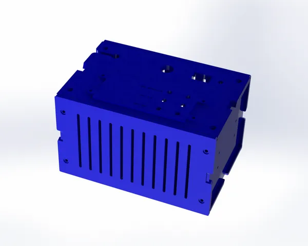
Case for Power Supply / Caja para fuente de alimentación
prusaprinters
- ESPAÑOL/SPANISH - Descripción:Se trata de una carcasa o caja creada para hacer fuentes de alimentación (para esos proyectos de electrónica).Contenido:- Rejillas para permitir su ventilación y no provocar un sobrecalentamiento.- Botonera principal que permite la incorporación de una abertura para el cable de la clavija que se conectará a tu toma de corriente doméstica, una abertura para incorporar fusibles, otra abertura para el botón de encendido y un pequeño orificio para el LED indicador de encendido.- Botonera secundaria que permite la incorporación de conectores banana hembra y su diseño puede variar de acuerdo a las necesidades de quien la usa, por lo que puede incorporar más entradas o algún espacio para perillas de potenciómetro o alguna pantalla LCD.Instrucciones de montaje:1.- La base es ensamblada por medio de las orillas que cuentan con dientes con un estilo de rompecabezas en las paredes de rejilla (dos de ellas) y la pared plana.2.- Primero ensamble las rejillas y después la cara plana (tenga cuidado, ya que en los extremos interiores de la rejilla tiene ranuras para que la cara plana y la botonera puedan deslizarse fácilmente).3.- Tenga cuidado de no romper las ranuras para tornillo en el proceso de ensamble. Verifique que los orificios o barrenos para los tornillos estén debidamente orientadas (que queden posicionadas en la parte exterior de la caja o ensamble).4.- Coloque la contra-base en el ensamble resultante de manera paralela a la base. Preste atención a los dientes de tipo rompecabezas ya que en un extremo no los tiene. El extremo sin diente de rompecabezas va orientado hacia el hueco formado por el ensamble actual. El lado que sí tiene el diente de tipo rompecabezas va posicionado en la pared plana.5.- Coloque la botonera principal en la cara faltante del ensamble resultante deslizándola (introduciéndola en las ranuras de las rejillas) desde la contra-base (ya que no tiene diente que obstruya su deslizamiento) hasta que embone en la base.6.- Si lo desea, asegure el apriete con tornillos de 3mm en los orificios destinados para ello ó colocando silicona caliente en las uniones.7.- Coloque la botonera secundaria en el espacio sobre la botonera principal y asegure por medio de tornillos o con silicona caliente.Nota: Es posible que necesite ajustar el contenido de la carcasa (los dispositivos eléctricos y electrónicos) antes de ensamblarla o asegurarla con tornillos o silicona caliente.Recomendaciones de impresión:Todas las piezas tienen una cara plana sin zonas en voladizo que requieran soportes, por lo que sobre esa cara se tendrán que colocar las piezas para su impresión.La botonera secundaria tiene letras que pueden no apreciarse adecuadamente cuando se imprimen, por lo que se sugiere un rediseño propio. - INGLÉS/ENGLISH - Description:This is a case or box created for making power supplies (for those electronics projects).Contents:- Grids to allow its ventilation and not cause overheating.- Main button panel that allows the incorporation of an aperture for the plug cable that will be connected to your domestic power socket, an aperture to incorporate fuses, another aperture for the power button and a small hole for the power indicator LED.- Secondary button panel that allows the incorporation of female banana plugs and its design can vary according to the needs of the user, so it can incorporate more inputs or some space for potentiometer knobs or some LCD display.Mounting instructions:1.- The base is assembled by means of the edges that have puzzle style teeth on the grid walls (two of them) and the flat wall.Assemble the grids first and then the flat face (be careful, as the inside ends of the grid have grooves so that the flat face and the button panel can slide easily).Be careful not to break the screw slots in the assembly process. Verify that the screw holes are properly oriented (positioned on the outside of the box or assembly).Place the counter-base on the resulting assembly parallel to the base. Pay attention to the jigsaw teeth as one end does not have them. The end without jigsaw teeth is oriented towards the gap formed by the current assembly. The side that does have the puzzle tooth is positioned on the flat wall.5.- Place the main button panel on the missing face of the resulting assembly by sliding it (inserting it into the slots of the grids) from the counter-base (since it has no tooth to obstruct its sliding) until it fits into the base.6.- If desired, secure the tightening with 3mm screws in the holes provided for this purpose or by placing hot silicone on the joints.7.- Place the secondary pushbutton panel in the space above the main pushbutton panel and secure with screws or hot silicone.Note: You may need to adjust the contents of the case (electrical and electronic devices) before assembling or securing with screws or hot silicone.Printing recommendations:All parts have a flat face with no cantilevered areas requiring supports, so on that face the parts will need to be placed for printing.The secondary button panel has lettering that may not show up properly when printed, so a redesign of its own is suggested.
With this file you will be able to print Case for Power Supply / Caja para fuente de alimentación with your 3D printer. Click on the button and save the file on your computer to work, edit or customize your design. You can also find more 3D designs for printers on Case for Power Supply / Caja para fuente de alimentación.
