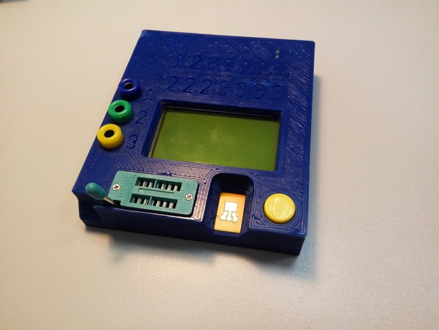
Case for LCR T4 component tester with Li-Ion battery
thingiverse
Compared to thing:797733 the following was added: Li-Ion battery with charger and step-up modules; Banana sockets for connecting probes. The OpenSCAD code was reorganized a bit to make adding other things easier: I use a center between PCB mounting holes as a reference point, instead of the center of LCD. Looks like my LCD is of the other model, and is a bit off, but the mounting holes are at their place anyway. Added pcblx - extra space on left hand side, for additional components like banana sockets. Some tweaks to allow adding components. Print Settings Rafts: No Supports: No Resolution: 0.4 Infill: 20 Notes: Printed with 0.5 nozzle and 0.4 layer height for speed. Assembling Hardware Requirements T4 LCR/transistor tester - I had version marked QS2015-T4; TP4056 Li-Ion charging module - I had one marked O3962A, if you have the other version You may need to change module dimensions and LED positions in powermod.scad (tp4056_pcb, led1_pos, led2_pos variables); MT3608 step-up module; 470 or 330 Ohm 0805 SMD resistor for LCD backlight; 6.8 KOhm 0805 SMD resistor to set TP4056 charging current; Prismatic Li-Ion battery. I used a battery from old mobile phone. The battery compartment size is 60x34x8mm, if your battery exceedes that, You may need to change dimentions defined in the prism variable in powermod.scad file. Some wire to make connections 4 x M3x16 flat head screws. Most of this stuff can be found on Aliexpress or Ebay. Also You will need the following tools: AVR programmer to flash new firmware - I used cheap USBasp programmer from Aliexpress; Some hookup wire, see here for ISP pinout and hookup example. Soldering tools Multimeter. Hardware changes Changing battery charging current Usually TP4056 modules come preset to 1A battery charge current which is too much for 800 mAh battery I used. To reduce it to match Your battery You will need to change the resistor connected between pins 2 and 3 of the TP4056 (R3 on O3962A module). I used 6.8k resistor, which gave me a charge current of about 175 mA. The formula for the charge current: Ibat = 1200 / Rprog Updating firmware New firmware should be flashed to the tester to support Li-Ion battery voltage monitoring. With stock firmware tester will think that battery voltage is too low for operation and will shut down. I put the needed files here and the procedure is described here. To connect the programmer to the T4 ISP pins you may use the trick with 3x2 pin header. Assembling Be careful to not to short anything in the process! Solder battery to B+ and B- pins on the charger module Check charging by connecting charger module to the USB Solder charger B- pin to step-up VIN- pin Temporarily connect step-up VIN+ pin to charger B+ pin Using multimeter and small screwdriver tune the voltage on the step-up VOUT+ and VOUT- pins to ~7V Disconnect step-up VIN+ pin from charger B+ pin Put all components in the case Connect all the needed pins to the T4 board as shown in the above picture. Note that discharge protection on the charger module is not used since mobile phone battery already has one inside. You may use two pieces of transparent 1.75 mm filament as a charger LED light conductors. References Original LCR T4 case with OpenSCAD sources LCR T3 and T4 schematics drawing by Roland Elmiger Interfacing LCR T4 ISP Changes to firmware, precompiled firmware for T3 and T4 variants. Reduce MT3608 module voltage ripple - in Russian. TP4056 datasheet
With this file you will be able to print Case for LCR T4 component tester with Li-Ion battery with your 3D printer. Click on the button and save the file on your computer to work, edit or customize your design. You can also find more 3D designs for printers on Case for LCR T4 component tester with Li-Ion battery.