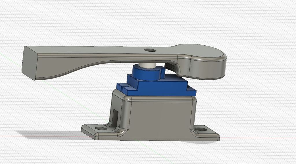
Cartesian / Prusa I3/ Anet / AM8 - Auto X-axis Level - Servo-Mount 2040 2020
thingiverse
On a Cartesian printer with two independent leadscrews for Z, it's common for the X-axis to tilt slightly, causing Z-wobbling artifacts. Heatbeds are often mounted on springs or silicone pads to allow for leveling adjustments. However, probing points on these floating beds can amplify errors from a crooked heatbed. I opted to use two independent points to align both Z-axes perfectly since I lacked space for a fixed point. To achieve this, I decided to utilize two servo motors in my project. For the servo motors, I utilized SG90-Servos that I purchased from Amazon (https://amzn.to/2CLuAIL). Here are some videos demonstrating similar setups: * https://www.youtube.com/watch?v=TvXCyZwuqzM * https://www.youtube.com/watch?v=e0h5YHoAH68 Since I'm using a DuetWifi Board, here's my configuration: 1. I assigned the Heater 4 and 5 pins (pin 13 and 18 of the expansion header) for use with the Servos. 2. To power the Servos with 5V, I used a buck converter. The case and converters can be found on Thingiverse (https://www.thingiverse.com/thing:3181309). Initially, you'll need to modify your config.g file to align the heater pins as PWM-pins for the servos: * M307 H4 A-1 C-1 D-1; Set Heater 4 to be PWM-Controlled (Servo Left) * M307 H5 A-1 C-1 D-1; Set Heater 5 to be PWM-Controlled (Servo Right) The Servos are moved using the M280 Code. For example, M280 P4 S25 I1 moves the left servo to an angle of 25 degrees, while inverting it. Be sure to send all commands as inverted to prevent the servos from malfunctioning. To prevent a crash on startup, I added the "move down command" (M280 P4 S25 I1 for the left servo) into the config.g file, ensuring that the Servos are always in the parking position. Remember that the right servo must move exactly opposite to the left one! The parking position for the left servo is at 25 degrees, and for the right servo, it's at 170 degrees. Next, I modified the bed.g file to enable auto-bed compensation. This code should give you a good starting point: * ; prepare auto bed compensation * G1 Y227.0 F12000; move bed out of the way * M561; clear any bed transform * M280 P4 S105 I1; left Servo Up * M280 P5 S83 I1; right Servo Up Now, let's get to the probing points: * G1 Z10; move 10 up to prevent a crash * G1 X-20.7 Y227.0 F12000; go to left Servo probing point * G31 P25 Z0; set trigger height to 0 * G30 X-20.70 Y227.0; define left Servo probing point as Z=0 Here comes the auto bed compensation: * G30 P0 X6.2 Y232.935 H0 Z-99999; probe point P0 * G31 P25 Z0.2075; set trigger height to 0.2075 (= hardware offset of both points) * G30 P1 X214.4 Y232.935 H0 Z-99999 S2; go to defined probing point 2 and do: S2 - Adjusting; S-1 Report Now, park the servos: * M280 P4 S25 I1; left Servo down * M280 P5 S170 I1; right Servo down Finally, reset the Z-height to normal: * G92 Z15; define z higher than normal to get a probe result * G31 P25 X+26.9 Y5.935 Z1.065; Z probe trigger value, offset in relation to nozzle. And trigger height adjustment -> reset to standard * G1 X83.1 Y104.065 F12000; go to the middle of the bed * G30 X83.1 Y104.065; probe the bed
With this file you will be able to print Cartesian / Prusa I3/ Anet / AM8 - Auto X-axis Level - Servo-Mount 2040 2020 with your 3D printer. Click on the button and save the file on your computer to work, edit or customize your design. You can also find more 3D designs for printers on Cartesian / Prusa I3/ Anet / AM8 - Auto X-axis Level - Servo-Mount 2040 2020.
