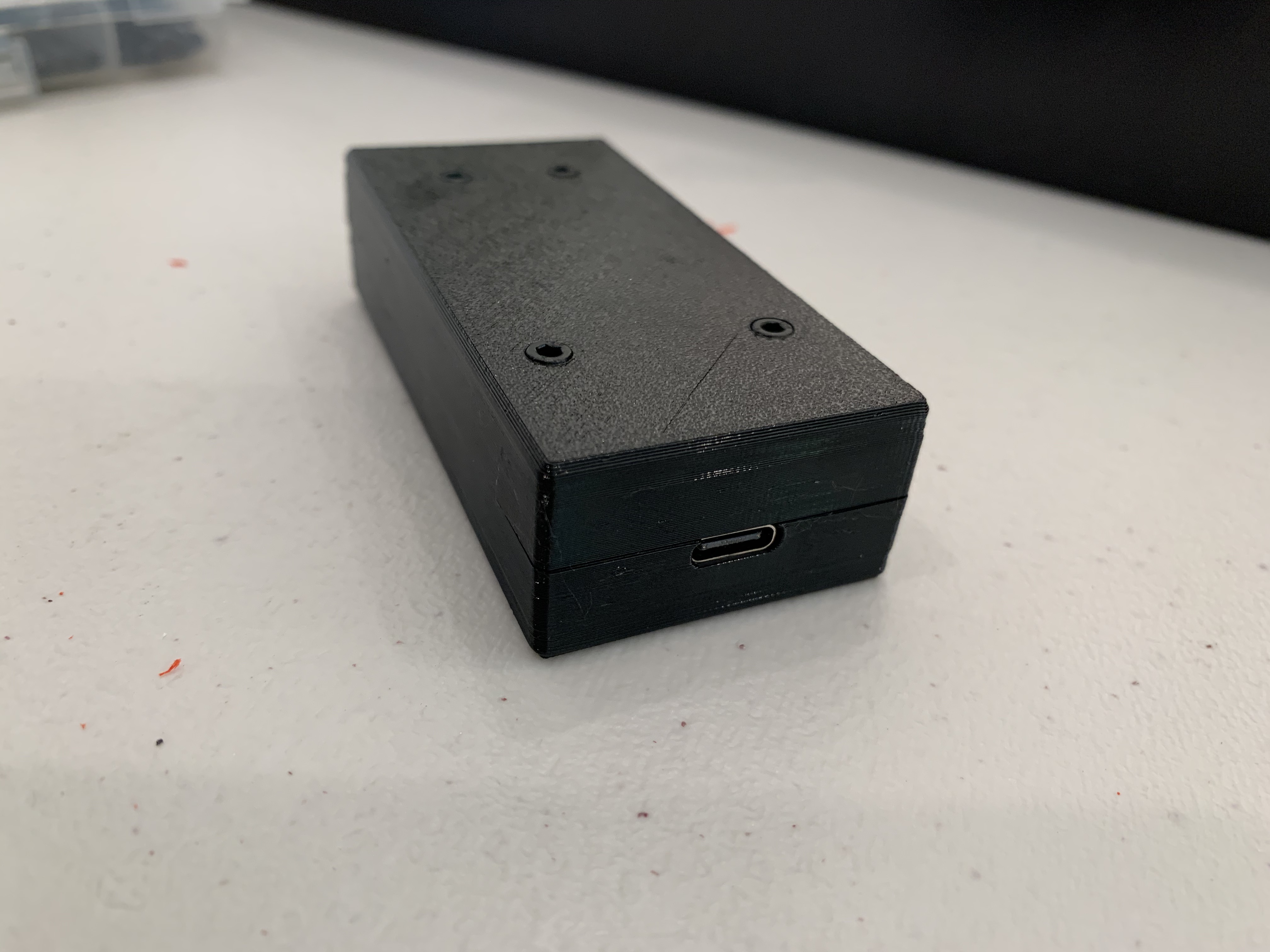
Carlinkit USB-C Case
prusaprinters
<p>I purchased a Carlinkit from here a few months ago:<br/> <a href="https://smile.amazon.com/Carlinkit-Wireless-CarPlay-Compatible-2017-2019/dp/B085VVCLKR/">https://smile.amazon.com/Carlinkit-Wireless-CarPlay-Compatible-2017-2019/dp/B085VVCLKR/</a></p> <p>A couple weeks ago it stopped working. Then I realize that if I moved the cable hard wired into it just so, it worked, and then if it moved it stopped working again.</p> <p>The customer service was going to be no help so I opened the thing up, to find that the usb dongle was not soldered in, it was connected to the board via a connector. So I bought a USB-C breakout board, snipped the end of the cable off, soldered the connections of the cables to the breakout board hooked it up, and it worked. Then I modeled this case, went through four iterations before I had something that worked.</p> <p>Note that you cannot print this in PLA because it is going in the car where it gets very hot (beyond the GTP of PLA).</p> <p>Requirements:<br/> You must own a soldering iron. If not, you can get a cheap one like this:<br/> <a href="https://smile.amazon.com/ANBES-Soldering-Iron-Kit-Electronics/dp/B06XZ31W3M/">https://smile.amazon.com/ANBES-Soldering-Iron-Kit-Electronics/dp/B06XZ31W3M/</a><br/> and some solder:<br/> <a href="https://smile.amazon.com/SONEAK-Solder-Rosin-Electrical-Soldering/dp/B084RZF23H/">https://smile.amazon.com/SONEAK-Solder-Rosin-Electrical-Soldering/dp/B084RZF23H/</a></p> <p>Parts needed:</p> <ul> <li>4x M2.5x18</li> <li>4x M2.5 Nuts</li> <li>1x M2.5x4 or 5</li> <li>USB-C breakout board. <ul> <li>I used this one: <a href="https://smile.amazon.com/gp/product/B07PVBM4FT/">https://smile.amazon.com/gp/product/B07PVBM4FT/</a></li> <li>it must be 16mm x 13.75mm x 1.57mm</li> <li>I provided the f3d file in the event that it is a different size</li> </ul> </li> </ul> <p>Note: I used this model in the process of building the case:<br/> <a href="https://grabcad.com/library/type-c-31-m-12-1">https://grabcad.com/library/type-c-31-m-12-1</a></p> <h3>Print instructions</h3><ol> <li><p>Print from the 3mf file or the gcode file. I set up some blockers you will need or else it tries to put supports in areas I found its impossible to get support out of.</p> </li> <li><p>Cut out the thin walls I put in the model to allow bridging, hence avoiding all the support in those areas. There are images from the slicer with red circles. This is where you want to cut out.</p> </li> <li><p>Solder the connectors to the breakout board. See the attached picture of the USB-C breakout board to learn which wire goes where.</p> </li> <li><p>Slide the breakout board into the top side of the case. Secure it in place with the M2.5x4 or 5 screw.</p> </li> <li><p>Use a screw from the opposite side to force the nuts into place in the top of the case (like how Prusa suggests when building an MK3).</p> </li> <li><p>Attach the wireless antennae which was previously stuck in place in the old case to the top side with the breakout board in it. Connect the connector from the breakout board into the main board.</p> </li> <li><p>Slide the end of the main board with a USB-A port into the end of the bottom side with the hole for the USB-A port. Screw all for screws into that side to secure the board in place and help align the screws.</p> </li> <li><p>Place the two pieces together and screw it together. Don't tighten TOO much or else you'll break the case.</p> </li> </ol> <p>You're done!</p>
With this file you will be able to print Carlinkit USB-C Case with your 3D printer. Click on the button and save the file on your computer to work, edit or customize your design. You can also find more 3D designs for printers on Carlinkit USB-C Case.
