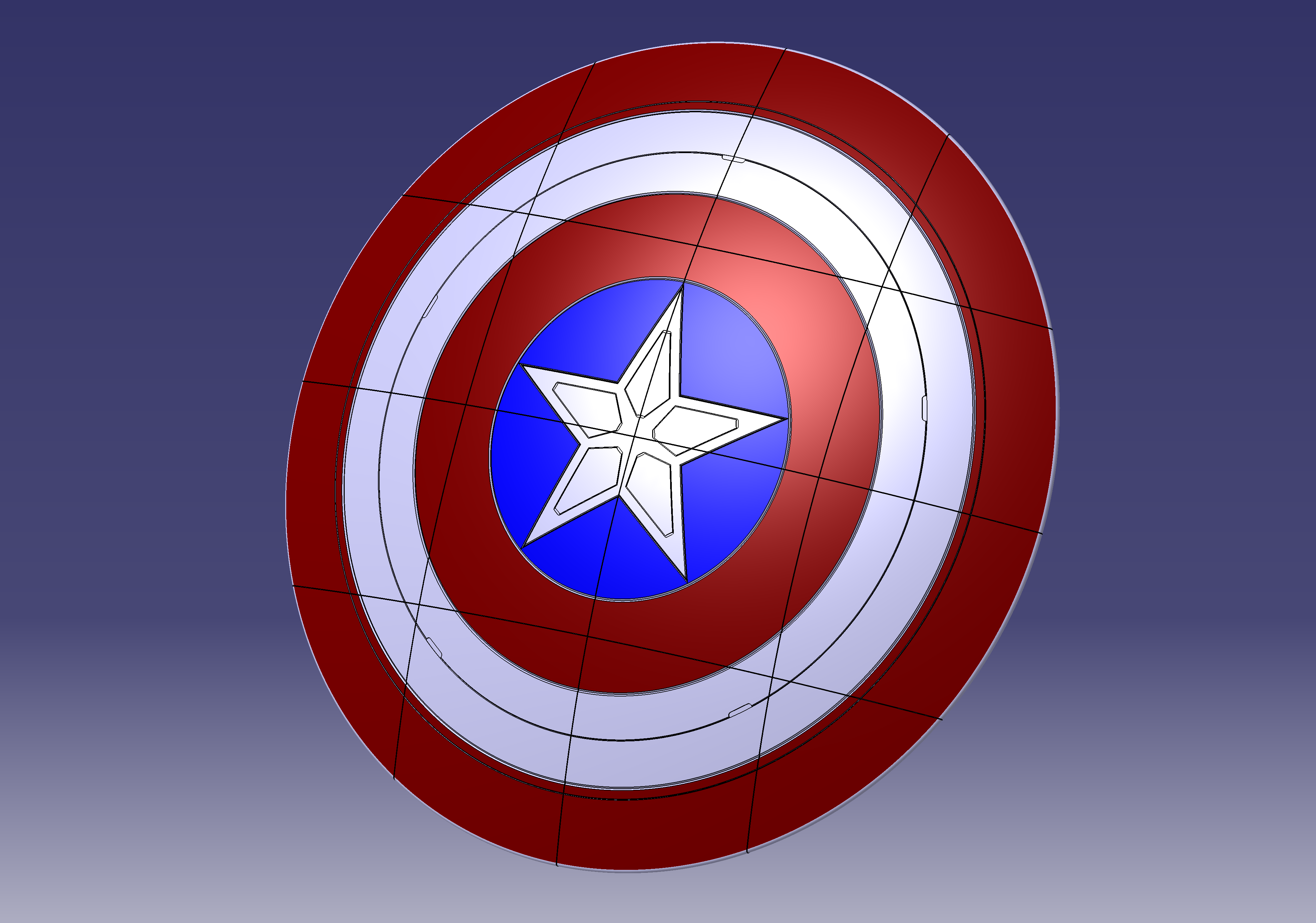
Captain America Shield (durable design)
prusaprinters
<p>This Shield was designed while keeping its strength in mind and serves as an example of a universal method to segment large parts into thin segments for 3D printing. </p><p>The diameter of the shield is around 650mm. I designed the front side myself and tried to be as close as possible to the original design of this version (I don’t know the right name of this version of the shield). I altered the backside and added a pattern to increase the strength while still being lightweight. I aimed to create a version that shows the strength of the method, therefore I am sorry that the backside is not close to the real version. I also added mounting points. My simple idea was to use those for M4 screws, which then allow the attachment of custom straps to mount the shield to the forearm. Additionally, someone could use the holes to design and attach a more advanced mounting solution. The placement of them is also adopted from a picture of the backside of the original shield I found online.</p><p>The design aims to produce an assembly with minimal loss to the performance and characteristics of a solid part. A hybrid joint combines adhesive bonding with press-fitting and allows for the force transmission, positioning, and assembly of the segments and can compensate for manufacturing tolerances.</p><p>Detailed information about the design method can be found in an open-access (free) publication I, together with my supervisors, published. I recommend taking a quick look at it to get a basic understanding of the design:</p><p><a href="https://doi.org/10.3390/designs6010002">https://doi.org/10.3390/designs6010002</a> @ @ </p><h3><strong>General/Printing Information</strong></h3><ul><li>The segments do not need supports except one) and are designed to be printed standing upright. Therefore multiple segments at once can be placed in the printing volume. For each segment, the printing direction is indicated in the following picture.</li><li><strong>!Important!</strong>: The one segment in the upper left, as indicated in the picture, requires supports, due to having to sides with a rabbet and no other possible orientation.</li><li>If you have problems with adhesion, I would recommend using a brim while printing. The mounting points on some segments protrude a lot. Maybe there are supports required to prevent the part from tipping over.</li><li>For optimal strength a 100% infill or increasing the number of walls is recommended. If a segment turns out thicker than expected, I recommend reducing the infill to 90% so there is a bit of space in the middle of the walls to accommodate access material. </li><li>Each segment is a bit different in size but every Segment is below 185mm x 185mm.</li></ul><figure class="image image-style-align-center"><img src="https://media.prusaprinters.org/media/prints/125141/rich_content/66da7319-23d4-456e-96fe-8c098f000b2d/print-directions.png#%7B%22uuid%22%3A%2249707000-5fab-4413-8ba1-90b615fcf901%22%2C%22w%22%3A3135%2C%22h%22%3A2445%7D"></figure><h3><strong>Assembly</strong></h3><ul><li>For the assembly, please refer to section 6.3. of the publication linked above.</li><li>In the current version, the segments are designed to work with 3mm x 30mm dowel pins. </li><li>We used a reamer with a diameter of 2.98mm or 2.99mm to rework the holes for the dowel pins. This achieves the perfect press-fit. As a more convenient alternative, I would recommend a reamer with 3mm. Even more convenient would be to use a 3mm drill. This probably results in a bit of play between the segments until the adhesive is cured. With careful placement, the overall shape should be fine.</li><li>If the Grid structure is in the way during pressing of the pins, simply use pliers or cutters to remove the section of the rib that is interfering. </li><li>Regarding the adhesive, I would recommend a two-component PU-adhesive for the best strength on most materials including PLA and ABS. Epoxy would be my second recommendation, but I do not have experience with it on this design. The gap between the overlap is (currently) 0.5mm. Therefore, a viscous adhesive is required.</li><li>To enable the compensation of printing tolerances, there is also a nominal gap of 0.5mm between every segment. This means if the length of a segment is 0.5mm too long after printing, there should be no gap between the two segments. If one segment is 0.5mm too short, you can adjust the gap to 1mm to achieve the right dimensions for the overall panel. </li></ul><h3><strong>Suggestions:</strong></h3><p>I would ask you to refer to the corresponding Reddit thread for suggestions. Alternatively, you can comment here. Then I can update the post with corrections or enhancements.</p><p><a href="https://www.reddit.com/r/3Dprinting/comments/seru3u/update_post_1_on_my_method_to_print_parts_larger/">Update Post 1 on my method to print parts larger than the build volume : 3Dprinting (reddit.com)</a></p><p> </p>
With this file you will be able to print Captain America Shield (durable design) with your 3D printer. Click on the button and save the file on your computer to work, edit or customize your design. You can also find more 3D designs for printers on Captain America Shield (durable design).
