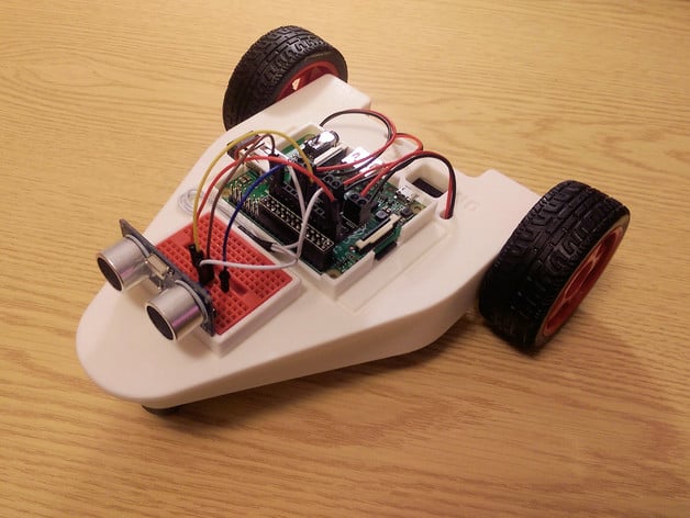
CamJam EduKit #3 Robot Chassis for the Raspberry Pi
thingiverse
The instructions provided are for assembling a robot using an EduKit kit, which seems to be a part of the Pi Wars competition. Here is a rewritten version in Markdown format: ### Step 1: Reaffixing the Battery Box - Remove any previously used battery tape and place double-sided sticky tape in the "STICK" area of the EduKit. - Align the battery box with its mounting holes on the robot chassis. - Screw down securely using provided small bolts. Choose a suitable screwdriver, as plastic threads are delicate. ### Step 2: Inspecting the Ball Bearing Holder - Ensure swarf (metal debris) is removed from screw holes in the ball-bearing holder recess. - If it was previously attached to another location, gently release the bearing by sticking your finger through the hole at the back. - Insert the ball-bearing holder into its intended position with screws pointing upwards. ### Step 3: Fixing the Ball Bearing Holder - To hold the ball-bearing holder in place securely, use provided small bolts. Be cautious not to over-tighten as it could damage the plastic or slip the bolt out. - Reinsert the ball bearing and test that it spins freely. ### Step 4: Preparing the Chassis for Pi Tray - Carefully cut away any excess plastic at the top of the chassis using a small craft knife. The aim is to clear enough space to securely place the Pi tray in its slot. ### Step 5: Positioning and Insertion of the Pi Tray - Hold the Pi tray by the GPIO side and align it with the slot. - If it's too loose, use a paper shim to increase the fit as you push it in. - Avoid using excessive force, as it might damage the components. ### Step 6: Preparing for Breadboard Clamp Installation - Use a craft knife or small tool to carefully remove excess plastic around the square slot intended for the breadboard clamp. - Positioning this area ensures easy attachment of both parts during assembly. ### Step 7: Installing the Breadboard and Clamp - Place the breadboard on its holder with text pointing up. - Ensure all edges align properly then slide it in so that the edges secure firmly. ### Step 8: Completing Motor and GPIO Connection - Before moving to wiring the line follower, ensure motor functionality by following CamJam worksheets or your own demo code on Raspberry Pi. ### Step 9: Finalising Line Follower Installation - Thread jumper wire through an unused slot near breadboard at the top of chassis. - Labeling each end of each jumpers helps keep the wiring organized in complex robotic setups. ### Step 10: Snap Finalising Line Follower Place and Attaching to Stud - If the plastic is too loose, carefully widen or bend it so the lines can rest neatly without being stretched out. - Once you've attached the final piece you can push everything into place ### Step 11: Finalizing the Ultrasound Sensor Installation (Optional) - Install it pointing forward into recesses near center. Once all components have been integrated according to the specified procedure and test functionality on demo programs; this project is ready for your creative exploration with line following code, motor control software integration, etc.,
With this file you will be able to print CamJam EduKit #3 Robot Chassis for the Raspberry Pi with your 3D printer. Click on the button and save the file on your computer to work, edit or customize your design. You can also find more 3D designs for printers on CamJam EduKit #3 Robot Chassis for the Raspberry Pi.