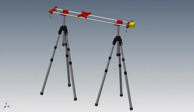
Camera Slider
prusaprinters
It is a motorized camera slider. See https://www.youtube.com/watch?v=Xh0SBud-Cfs. First the slider is running on slowest speed, then full speed and slowest speed again. I used the original thing as an example but changed a lot. You can put it on the ground, on one stand or 2 stands. I use 2 stands because there will be a little movement because of the weight when the camera is at one side. It depends on the weight of the camera. It also depends on the connection with the stand. The 2 rods bases (where the stands are connected) can move. You don't have to use glue like the original one. A BOM list is added. Don't pay attention to the DIN or ISO numbers of the bolts and nuts. I used a dc motor with gearbox. But there is also a mount (slider-motor.stl) for a NEMA 17 stepper. I used a 80 RPM DC motor, but you can use of course a slower or faster motor. There is also a open mount for the DC motor (slider-dcmotor.stl) I will use an Arduino with motor driver (30A Mini VNH2SP30 Stepper Motor Driver Monster Moto Shield module For Arduino) to drive the motor. Intention is to add an app connected with bluetooth. It is not ready yet. I will add later some details. You can also use a 6-30V DC Motor speed Controller Reversible PWM Control Forward / Reverse Switch to control the motor. Then you don't need the limit switches of course. But you have to stop the motor on time :-). Running on a 5V battery pack is not working right now. The motor driver needs at minimum about 5.2V. For this moment I use 10V for the motor and 5V for the Arduino. We use 2 USB battery packs for making 10V (in serie) and one of these 2 are used for Arduino 5V. Maybe we will try later with a step-up regulator and 1 5V battery pack. The belt is connected to the platform on the left and right. Just by inserting it double folded. See pictures. The belt can be put on tension with the 2 screws in the belt wheelholder. Don't tension it to much. I use a rubber band (from the postman) around the platform to trigger the limit switches which gives some flexibility. You can use it without. But on full speed the DC motor will take a little more time to stop then a stepper motor. With the rubber band it will not run into the limit switch. On lower speed this is not necessary. It is still work in progress but the 3D printed parts will be ready (I think). Edit: 14-4-2017: Added diagram of electronics. Also in the diagram LANC control for my Sony camera is added. You can leave this out if not needed. It is used to take pictures automatically at a defined interval. I used a Arduino Nano, Bluetooth HC-05 module and 30A Mini VNH2SP30 Stepper Motor Driver Monster Moto Shield (like this one http://www.ebay.com/itm/152234873766). Arduino software will be uploaded later here. 26-4-2017: Arduino software is added. No guarantees for the software :-) Probably not most efficient coding but it is doing what I want. Following commands are possible: (output will also presented when connection terminal to serial port arduino) Action commands: 1# STOP all2# Move FORWARD (away from motor side) 3# Move REVERSE (towards motor side)5# Move continues run (without pause) 6# Move start/stop with pause and running delays; Continues runP# Take photo U# Switch camera offA# Switch camera on I# Switch camera on, take photo, switch camera offFxxxx# Start take photo every xxxx in seconds without moving. Will stop current move action G# Move start/stop with pause and running delays and take photo just after moving; Continues runL# Calibrate. Measure time (ms) to move from one side to the other side at current speed Settings commands: D# Set direction forward (away from motor side)E# Set direction reverse (towards motor side) +# Increase speed with +5 (000-255)-# Decrease speed with -5 (000-255) Sxxxx# Set speed 0001 - 0255 (min = 0030)Bxxxx# Duration of pause in start/stop run Cxxxx# Duration of running in start/stop runHxxxx# Stop everything after taken xxxx photos (only STOP action will reset this) J# Get current speedK# Get number of photos taken Commands can be given through bluetooth or serial port (USB Arduino Nano). Just try and have fun. We are still working on the android app which will connect with arduino by BT. Camera functions are for Sony LANC camera. Print Settings Printer Brand: Prusa Printer: Prusa Steel Rafts: No Infill: 20% Notes: All parts have a tight fit. I didn't need to adjust the printed parts to fit. I printed it with PLA with 20% infill mostly. Also mostly without support. It also depends on your printer. Also watch the orientation of parts in the stl files. You have to place it the right way on the bed. You have turn it sometimes 90 or 180 degrees. Some printing remarks: slider-platform: put the side with the place for the nuts above. slider-dcmotor-box: side with the motor mount down slider-holder: flat side down slider-rods-limit-switch: on the side (i used support for where the PCB is mounted) slider-rodsbase: on the side slider-roller-wheel: I used support Post-Printing Just put it together. See video. How to put it together. How I Designed This I designed this with the original thing as an example. I changed a lot. Category: Camera
With this file you will be able to print Camera Slider with your 3D printer. Click on the button and save the file on your computer to work, edit or customize your design. You can also find more 3D designs for printers on Camera Slider.
