Cageless, Multilayered, Full Complement Axial Tapered Roller Bearing
grabcad
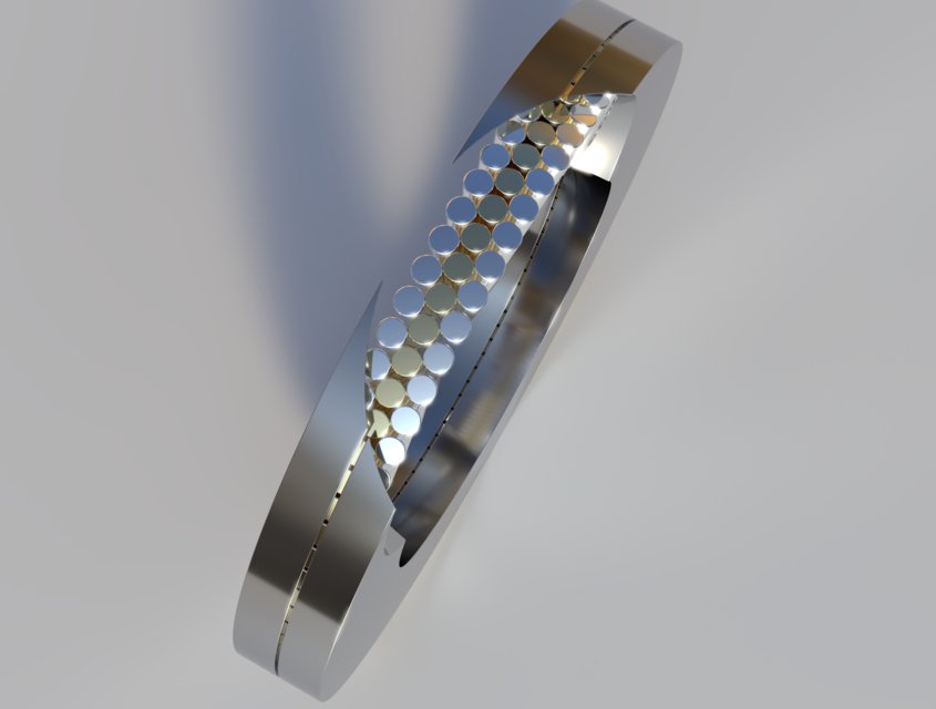
Third of several different rolling element bearing concepts I came up with back in late 2013 - early 2014. Unlike the first and second designs, this one is an axial bearing, meant to primarily support axial loads. However, it likewise features the unique trait of employing three stacked layers of intermeshing interspersed rolling elements rather than just one. But these are now tapered cylinders rather than uniform cylinders or spheres and are arranged in a radial pattern converging on the bearing's axis of rotation rather than being arrayed parallel to it. As with the other two bearing concepts, the middle layer of rollers serves as a sort of rolling, load-bearing cage keeping consecutive rolling elements in each of the other two rows from coming into contact with one another while its own consecutive rollers are kept separated by those in the other two rows. The middle layer of elements also conveys load between the other two as well, just like in the other two designs. It's necessary for the rollers to be tapered because they need to roll in a circle around the bearing's center while pointing towards it rather than rolling in a straight line always parallel to the bearing's axis of rotation and never pointing to it, as in the radial roller bearing concept. As such, the end of each roller facing the center of the bearing needs to have a diameter proportionally smaller than its opposite end which is facing away so that it naturally wants to roll in a circle rather than in a straight line. As with the first bearing concept, the bearing should inherently automatically adjust for slight differences due to manufacturing tolerances in the respective diameters of its various rolling elements and also spread the axial load evenly across all of its rollers. If rollers in the top and bottom layers in a particular sector of the bearing are experiencing higher loads than elsewhere or than the average over all of the bearing's rolling elements, they get pushed down and closer together in that area. In the process, they cause rollers in the middle layer to get pushed out sideways and closer together elsewhere in the bearing which causes corresponding rollers in the top and bottom layers elsewhere in the bearing to get spread apart away from each other and get pushed up against the bearing's axial load of which they consequently pick up a larger proportion than they did before. Until the load has spread evenly to all rollers in the bearing and stabilised, this mechanism should ensure both automatic self-adjustment to compensate for slight differences in the respective diameters of the various rollers in the bearing as well as evenly distribute load to all rolling elements in the bearing. Even so, it would probably still be necessary and advisable to try and center axial loads on the bearing as much as possible and practical. As with the radial roller bearing, an even number of layers of rolling elements cannot be used because it would convey rotation from one of the bearing's surfaces to the other defeating the purpose of the bearing and that of using rolling elements inside of it. And a single layer of rollers would be no different from tapered roller axial bearings currently in widespread use which exhibit sliding contact either between consecutive rollers in the one layer of rolling elements or have sliding contact with a cage which keeps them separated from each other but which they all slide or rub against contributing to friction heat and wear.
With this file you will be able to print Cageless, Multilayered, Full Complement Axial Tapered Roller Bearing with your 3D printer. Click on the button and save the file on your computer to work, edit or customize your design. You can also find more 3D designs for printers on Cageless, Multilayered, Full Complement Axial Tapered Roller Bearing.