Cable gland "all sizes"
prusaprinters
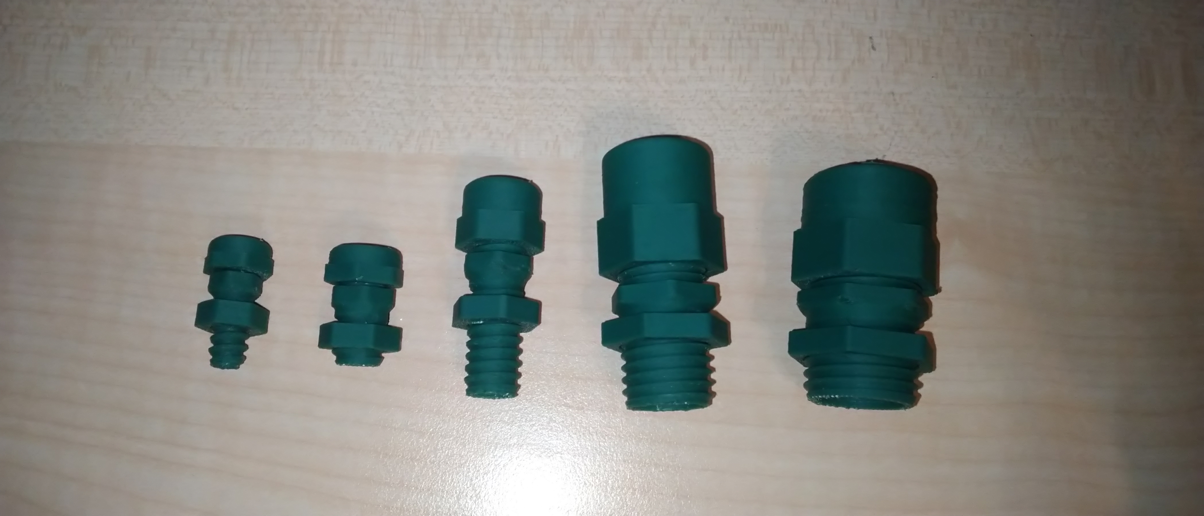
<h3><strong>What and why?</strong></h3><p>Since i have been asked about my other design of cable glands if it could be available in other sizes, I thought about in and designed a parametric model. This didn't take long. Exporting the stl for all sizes was a bit underestimated by me and takes much longer…</p><p>I uploaded only 300+ sizes here since exporting all those STL takes some time. If you need a different size just comment which one and I'll export it as well. That's also why i didn't upload a step file this time. I only have my parametric NX file here which most people probably can't use.</p><p>It is designed to work without the rubber seal and just be able to push the cables through, screw on the top-nut and fix everything in place by this. The way how it was designed and depending on the material the libs may break while clamping the cables down too far (happend to me once). It will still work and hold down everything as the clamping mechanism wont be effected. Only after disassembly this will make issues. Therefore it wont be reusable that often as bought ones probably.</p><h3><strong>Parameters?</strong></h3><p>The <strong>D</strong>-Parameter in the Name stands for the inner Diameter. So measure your Cables (or other parts) and decide on the correct diameter you need. The size reduction will be different depending onto the D size. Bigger glands simply can get reduced more than the smaller ones. I just have a few tested numbers here: D3.5 → 2,6mm; D5.5→ 4mm; D8→6,3mm; D18→14mm</p><p>The <strong>L</strong>-Parameter in the Name stands for the length of the back thread which will go though the wall or the panel. Choose it by your panel thickness - 6mm (the nut is 5mm thick +1mm thread safety).</p><p>The hole diameter in your wall will always be <strong>D</strong> + 5mm. The thread was designed to always stay 5mm bigger than the bore.</p><figure class="image image_resized image-style-align-center" style="width:18.02%;"><img src="https://media.prusaprinters.org/media/prints/114283/rich_content/069f2c6e-9851-4d55-8c7d-eaaf6bdb7bb9/masse.png#%7B%22uuid%22%3A%2276437382-c80b-4af3-acda-1c567dcd805a%22%2C%22w%22%3A326%2C%22h%22%3A676%7D"></figure><h3><strong>Printing:</strong></h3><p>Didn't test all models but i printed a few of them and they work well for me. You can find the pictures attached.</p><p>Printed them is not always that easy (especially the thinner diameters). Following setting were working well for me when using ABS:</p><ul><li>Layer thickness 0.1-0.15 (for nice thread geometry)</li><li>Extrusion width 0.42 (0.4 nozzle since the walls are not that thick)</li><li>2-3 Contour lines (at least filling it up 100%)</li><li>265°C hotend (for good layer adhesion with ESUN ABS + )</li><li>80-100 % cooling fan speed and open enclosure ( yes even with ABS) to make sure that especially these small thin parts get printed nicely. Warping e.g. shouldn't be an issue because the parts are too small and thin. </li><li>Bed temp 80°C also to make sure that the thin parts cool down fast enough without deforming but still deliver some adhesion.</li><li>A raft layer for the middle part because it is quite high and has nearly no real bottom surface.</li></ul><p>Other Materials will definitely also work with some testing, but i didn't try it yet. Would be nice if you share Information about it in the comment section once you have printed it.</p>
With this file you will be able to print Cable gland "all sizes" with your 3D printer. Click on the button and save the file on your computer to work, edit or customize your design. You can also find more 3D designs for printers on Cable gland "all sizes".