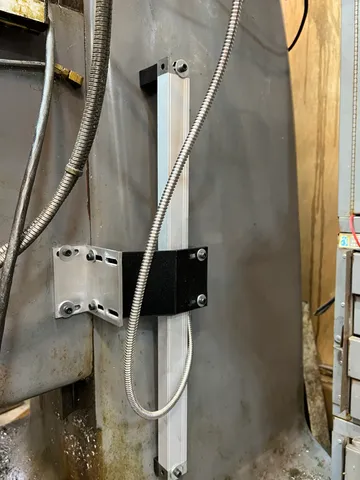
Bridgeport or Knee Mill Z axis DRO Brackets
prusaprinters
The top and bottom spacers have two M6 socket head cap screw clearance holes spaced 19mm apart. These holes are used to mount the spacer to the base casting. In the center of each spacer is a M5 tap drill hole. Tap this to allow the scale to mount onto the spacers with a M5 bolt. The bracket has 2 pairs of M5 slots. These slots are spaced 60mm apart. This spacing was chosen because this is the spacing of the holes on my DRO scale. (ToAuto optical 400mm travel). The bracket shown attached to the actual knee was included with my DRO scale. The spacers have a 3.6 degree angle on their mounting face. This comes from measuring the angle of my base casting in relation to the angle on my knee. Your mill may be different. The difference in length of each spacer comes from trigonometry. My bolt holes on my DRO are 519mm apart. At a 3.6 degree angle this comes out to a difference of ~33mm. I've included the .stp files for you to modify the spacers to match your scale's length as well as your mill's casting. Its crucial that the scale be mounted perfectly parallel to the mill's knee's travel. Otherwise you'll get cosine errors in your readings.
With this file you will be able to print Bridgeport or Knee Mill Z axis DRO Brackets with your 3D printer. Click on the button and save the file on your computer to work, edit or customize your design. You can also find more 3D designs for printers on Bridgeport or Knee Mill Z axis DRO Brackets.
