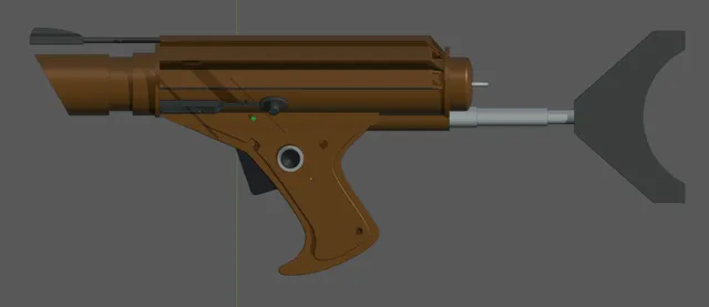
Blake's 7 Federation Trooper Blaster
prusaprinters
Edit - 18th September 2022 - Got my extruder working again now so I have done a test print. That has resulted in a couple of tweaks, mainly for fit. I've made the trigger thinner to let it move easier (now 5.6mm instead of 5.95mm). I have also modified the grip frame to allow more clearance around the Friedland button. The originals fit fine but once in were difficult to remove. I've also updated the 3mf file with the new versions. This model uses a Friedland button like many of the props used on the show. I have not included one in this upload as one is already available to print https://www.printables.com/model/115390-blakes-7-friedland-button-working if you cant find a real one.Most of the parts are capable of being printed without supports if oriented correctly. I have included a Prusa Slicer (v2.4) project with my suggested orientations and supports already defined for those parts that need them. The parts are grouped by colour, so black, silver and brown.With a few exceptions.The Main Body has a small section at the rear.The Power Cell Cap needs a bit of support for the Ring HolesThe Grip Frame is the part that needs the most extensive supports. The Esso Disc detail part due to its shape is best printed at an angle with a bit of support just to hold it in place. Required HardwareSmall spring (as found in some retractable biro pens)M3x20 Cap head socket screwM3x14 Countersunk socket screw2x M3x6 Countersunk socket screw4x M3 square nuts (as used in the Prusa MK3 build)2mm pin (or screw) to act as a trigger pivot/hinge3x M2x10 Countersunk self tapper screws.2x disc magnets (optional for the Power Cell, should be 6mm diameter by 3mm thick)Glue (some parts are glued together, I used a superglue on my pla test print)Optional HardwareI have included a printed version of the Front Sight rod, this is a 4mm diameter rod 100mm in length. I suggest using a metal 4mm rod cut to length which is what I'm using on my build. It will be MUCH stronger.The original Stock was a telescoping type, probably an antenna. What I have done is to include 3 diameters of tube. These are designed to have some M5 threaded rod put inside with nuts on each end to give it strength. This will make the stock more practical. You can scale the tubes in length (Z) to adjust the stock length to your preference and use whatever length you need of threaded rod.3mm metal wire to form a replacement for the Power Cell Loop. While a modelled one is provided this is another part that would be better replaced with metal for durability. Just bend it to shape to match. Assembly InstructionsThis goes together in a very similar fashion to the Officers pistol.The grip is joined to the main body using 2x M3 (the 20mm cap head in the front and the 14mm countersunk at the rear) screws and 2x M3 square nuts. One of the nuts slides into the front of the barrel tube. Slide it in until it lines up with the hole.The second nut goes into the rear of the grip from the side. To allow holes to be printed without support a 1 layer (0.2mm) thick layer was added so that it would bridge if the orientation requires it. You should be able to poke through those layers very easily. IInsert the spring between the trigger and the grip on to the posts modeled in. Then squeeze the trigger into place and add the pin. Check that it moves freely and that the spring returns it to the rest position.Glue the Friedland switch body and button into place in the hole on the side of the Left grip panel.The front of the grip uses the M3x20 Cap head screw going through the grip and into the body. The back of the grip goes from inside the body (where the power cell fits) and down into the grip. This one uses the M3x14 countersunk screw. There is a small hole in the top of the body to allow the Allan/hex key to fit and reach the screw to tighten this if the Power Cell is not in the blaster.Towards the bottom of the grip are slots for the last 2 M3 square nuts. These are form the grip side panels.The left and right grip panels go into slots in the main body to hold the tops and then you can use the M3x6 countersunk screws into the square nuts in the lower part of the grip. The same front screw that holds the grip on will also go into the barrel inner to hold that in place. Once you have the barrel inner screwed in you can then glue on the Barrel Disc. It has a locating lug to make sure it goes on in the right orientation. Just a tiny bit of glue is needed as its not structural and just needs to hold in place.Then the barrel Muzzle can slide on from the front. You can use another of the small countersunk self tapper screws on this in the hole provided or you can glue it in place (or do both).If you need to remove the barrel for any reason you can simple back off the front screw from the grip and the barrel assembly should be removable.The sight blade should be glued to the sight rod and then that glued to the main body. The various black detail sections should be glued onto the side of the Main body next. The Power Cell You can use a couple of disc magnets to secure the power cell in place. I've also modelled in a small hole for a m2 countersunk screw to hold it if you don't want to use magnets to hold it.Glue the Loop into place (either the printed one or a metal one)Glue the Power Cell interior into the end cap. If using magnets to hold it in place then glue one into the nose of the power cell and the other into the sled. Make sure the magnets are the correct way round to attract and not repel each other (trust me I've done this wrong before lol).Then you can fasten the sled into place in the body.A note about the sled - this project is designed with fitting electronics into it in the future. Its why the sled has cut outs for a circuit and a small 20x40mm speaker. Its also why there is space for a tactile switch in the grip. I haven't finalised that version yet though. The Power Cell interior will be replaced with a different part to hold the battery eventually.You can then glue in the stock tube assembly to the Main body and attach the Stock itself to the tubes using another of the self tappers or more glue if you want.Designed in Blender
With this file you will be able to print Blake's 7 Federation Trooper Blaster with your 3D printer. Click on the button and save the file on your computer to work, edit or customize your design. You can also find more 3D designs for printers on Blake's 7 Federation Trooper Blaster.