Bearing 1
grabcad
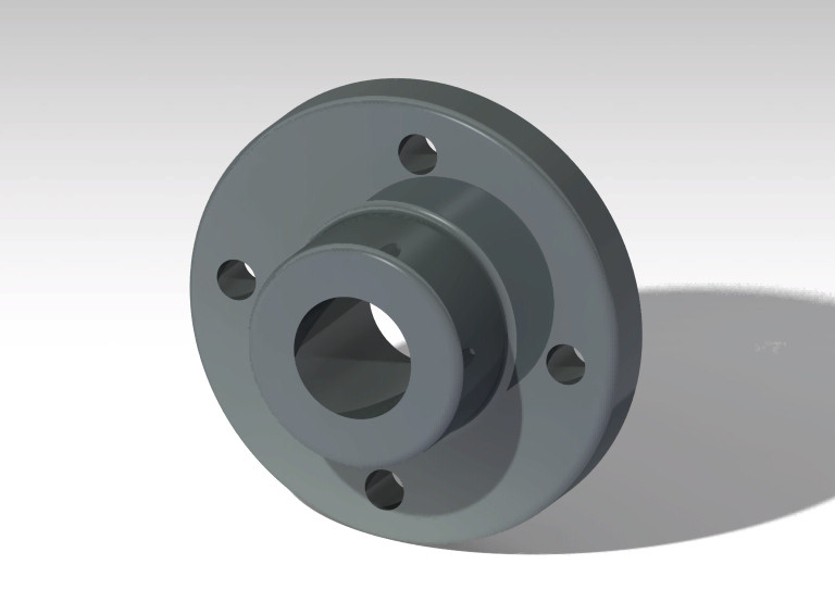
Designing a bearing using CATIA V5 is an exciting project that requires careful planning and execution. To get started, first, open up the CATIA V5 software and create a new part document. This will serve as the foundation for our bearing design. Next, select the "Part Design" workbench from the top menu bar and click on the "Create Body" button to launch the body creation tool. This tool allows us to define the shape of our bearing by specifying its dimensions, materials, and other relevant properties. In this tutorial, we will be designing a simple ball bearing with a cylindrical outer shell and an inner ring that supports a set of balls. To begin, click on the "Cylinder" button in the body creation tool and specify the diameter and height of our outer shell. Make sure to select the correct units of measurement for your design. Once you have defined the outer shell, move on to designing the inner ring. Click on the "Ring" button and specify its dimensions, including the outer diameter, inner diameter, and thickness. You can also add holes or other features as needed. Now that we have our bearing's main components designed, it's time to assemble them together. Select the "Assembly Design" workbench from the top menu bar and click on the "Create Assembly" button to launch the assembly creation tool. In this tool, you will be able to define the relationships between our various parts, including the outer shell, inner ring, and balls. Make sure to specify the correct constraints and relationships to ensure that your bearing design behaves as intended. With our assembly complete, we can now perform some simulations to test its behavior under different loads and conditions. Click on the "Simulation" workbench from the top menu bar and select the type of simulation you want to run, such as static or dynamic analysis. Finally, once you have completed your bearing design and simulations, it's time to document your results. Select the "Drafting" workbench from the top menu bar and click on the "Create Drawing" button to launch the drawing creation tool. In this tool, you will be able to create a 2D representation of your bearing design, including its dimensions, materials, and other relevant information. Make sure to include all necessary views, notes, and annotations to ensure that your drawing is complete and accurate. That's it for this tutorial on designing a bearing using CATIA V5! I hope you found this guide helpful in getting started with your own CAD design projects. Don't forget to subscribe to my YouTube Channel 'CAD CAM CAE Learning Solutions' for more updates on software tutorials and design projects.
With this file you will be able to print Bearing 1 with your 3D printer. Click on the button and save the file on your computer to work, edit or customize your design. You can also find more 3D designs for printers on Bearing 1.