Bear 2.1 micro-adjustable X ends
prusaprinters
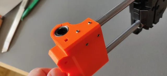
Rework of the original X ends by gregsaun for the MK3 Bear 2.1 full upgrade with parallelism adjustment of the rods.This mod allows ~400µm of vertical adjustment of the bottom rod on either end (+/-200µm from the exact position).It's a common problem to have binding of the X carriage towards the ends due to either carriage or (more commonly) Z shrinkage after print. While normally tolerable with linear bearings, the added friction becomes a true problem for polymer bushings that require perfect or almost-perfect tolerances. These ends allow for perfect parallelism adjustment tailored to your carriage, however it does require significant patience during assembly.BOM:4x M3x6 cup-point grub screws4x M3x3 cup-point grub screwsThin HDPE/Kapton/paper strips for additional shimmingPrinting:Print X ends with the same parameters as for the original (0.2mm layers, 4 perimeters, 20% infill, 5 top/bottom layers).Print “shims” with 0.15mm layers, 5 perimeters with “Detect thin perimeters” option enabled (or use the Arachne perimeter generator for a similar result).After printing, cleanup the rod holes carefully and ream the top hole with a 8mm drill if necessary, ensuring no residue is left on the cavity. Do not ream the bottom hole.Use an M3 screw to tap the 8 holes for the grub screws (2 bottom, 2 side for each end). Do 3 passes for each hole in order to have a tight, but clean thread. Do not use an M3 tap: the resulting fit is too loose at these shallow depths and would require additional screw-locker. Cleanup internal residue.Assembly:If you're installing polymer bushings and want to have precise results, parallelism needs to be adjusted to your printed X carriage. It will be assumed you have already experience assembling/servicing the whole X carriage here.On the bottom rod the grub screws will be touching the metal directly and could damage the hardened surface. This is not a problem usually as the end of the rod is not a sliding surface, but if you want to avoid that an additional shim is needed. I used 2 layers to Kapton tape (3cm strips of 4mm in width directly taped on both ends), but you can also insert paper strips or some thin HDPE film later.Take the X motor end and insert the top and bottom rods. Mind the Kapton shim which should be aligned on the bottom at this stage. Insert the bearings/bushings (2 top, 1 bottom), then complete the linkage by inserting the X idler end. Wiggle the ends and level them flat.Insert the printed shim on the top corner of the bottom rod. The “dot” (printed on one end of each shim) should be inserted first. If you are using paper/HDPE shims, you should now insert the paper on the bottom side of the rod.Mount your X carriage back&front plate and fully tighten the bearings in place. Move the assembled carriage left to right a couple of times in order to level the rod distance. The carriage should be butter smooth. Move the carriage towards one end (leaving minimal space) and measure with a caliper the outer rod distance. Repeat the step on the other end and ensure you get exactly the same and repeatable measurements. Note this distance now.Insert the grub screws: M3x3 on the bottom holes, M3x6 on the side holes and screw them halfway.Start with one end and tighten the two bottom screws until the distance between the rods is about 0.04-0.06mm shorter than optimal. Doing so requires turning the screw ~¼ of a turn, then moving the carriage (to remove any slack) and then repeating the measurement. After this, start tightening the side screws again ~¼ of a turn at a time to push the rod outwards. After each tightening step, slide & repeat the measurement until the distance is exactly as initially measured. Wiggle the ends and level them flat. Repeat the measurement to ensure it hasn't changed.If the distance it too large, back down ¼ of a turn of the side screws. If that doesn't reduce the distance, some space has been eaten by the bottom shim: do a ¼ turn of the bottom screws instead. Proceed slowly, since it's quite easy to deform the plastic part. Repeat the same steps on the ether end.
With this file you will be able to print Bear 2.1 micro-adjustable X ends with your 3D printer. Click on the button and save the file on your computer to work, edit or customize your design. You can also find more 3D designs for printers on Bear 2.1 micro-adjustable X ends.