Base para corte modelo
grabcad
Example piece for a five-axis milling tutorial using SprutCAM. In this example, we will create a simple part that demonstrates how to use the various features of SprutCAM's five-axis machining module. The part is a small cube with a hole drilled through it. To start, open up SprutCAM and create a new project by clicking on "File" > "New Project". Choose the "Milling" option from the list of available project types, then select "Five-Axis Milling" as the machining type. Next, define your machine tool and cutting tool settings by going to "Machine" > "Machine Settings". For this example, we will use a standard five-axis milling machine with a spindle speed of 1000 RPM and a feed rate of 100 mm/min. Now that our project is set up, it's time to create the part. In the "Model" tree, right-click on the "Part" node and select "Create" > "Cube". This will insert a new cube into your model with dimensions of 20mm x 20mm x 10mm. To add a hole to our cube, we need to create a feature. In the "Feature" tab, click on the "Hole" button and select the type of hole you want to create (in this case, a cylindrical hole). Define the hole's parameters such as diameter, depth, and location. Once you have defined your hole, you can add it to your part by clicking the "Add Feature" button. This will insert the hole into your model. With our part created, we are now ready to start machining it using SprutCAM's five-axis milling module. To do this, go to the "Machining" tab and click on the "Five-Axis Milling" button. Select the cutting tool you want to use (in this case, a standard end mill) and define your machining parameters such as depth of cut, feed rate, and spindle speed. Now that we have our machining parameters set up, it's time to create the milling operation. In the "Operation" tab, click on the "Milling Operation" button and select the type of milling operation you want to perform (in this case, a standard face milling operation). Define the operation's parameters such as feed rate, spindle speed, and depth of cut. With our operation created, we can now run it using SprutCAM's simulation mode. To do this, go to the "Simulation" tab and click on the "Run Simulation" button. This will simulate the machining process and allow you to see how your part will look after it has been machined. That's it! With these simple steps, you have successfully created a five-axis milling tutorial using SprutCAM. You can now use this example as a starting point for creating more complex parts and machining operations.
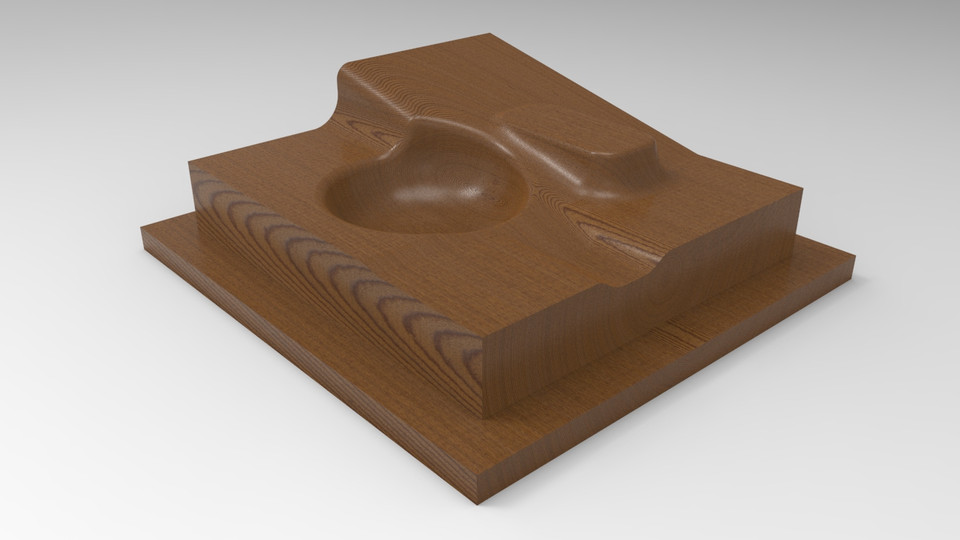
With this file you will be able to print Base para corte modelo with your 3D printer. Click on the button and save the file on your computer to work, edit or customize your design. You can also find more 3D designs for printers on Base para corte modelo.