Azimuth/Altitude mount for the Hadley 114/900 telescope
prusaprinters
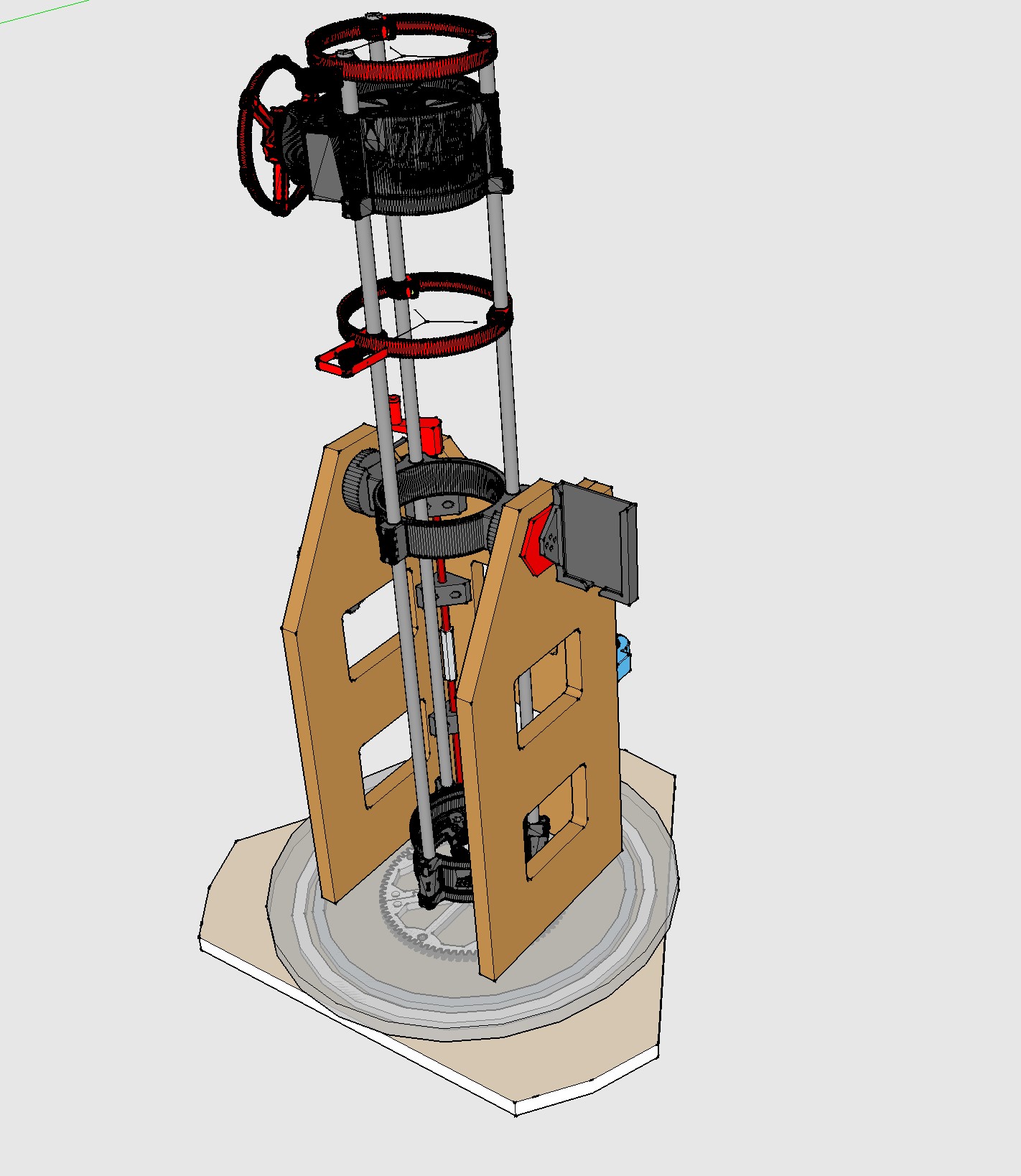
<p>CHANGELOG:</p><ol><li>07.12.22 uploaded stl/3mf revised Dovetail Female parts, changed to include thumb screws to lock down the scope in the dovetails and stiffen up the overall assembly. Big improvement. Left the original versions up. I am using an M5x25 hex head bolt with printed thumbscrew heads from, the primary mirror cell (different posting). See new pic.</li></ol><p> </p><p>Printed out and assembled the Hadley telescope by Maff and as I was doing so I was also looking into what a Dobsonian mount is all about, since that was what Maff has the scope set up for. I see a lot of people using them out there so they must work OK.</p><p>Because I can never leave well enough alone, I chose instead to design and build my own version instead. The Dob mount just seems way to MACRO in how you adjust the elevation by simply pushing and pulling on the scope to roll it around the half-moon plywood bearing surfaces. That wasn't gonna work for me, so off to the chalkboard I went.</p><p>When the dust cleared, I ended up with a version that uses the same basic principle (a wood support structure) but added gearing adjustment systems for both axis, a dovetail system to accept the scope and a bunch of various printed pieces for doing this and that.</p><p><i><strong>THE WOOD:</strong></i></p><p>I originally intended to make the two horizontal pieces out of plywood, but since plywood is liking freaking gold right now I was able to purchase these cool premade rounds (top is 18" and bottom is 24") from Lowes for less money than a quarter sheet of ¾" plywood would have cost me. they are a full inch thick which is pretty nice, and you don't even have to cut the circles which is even better. Obviously you can do whatever you want here and could even go smaller if you want, but the 18" is about right. As you can see, I chopped the corners off of the 24" to make it weigh a little less, be less prone to bumping into and becasue it looks cool.</p><p><a href="https://www.lowes.com/pd/Radius-Edge-Unfinished-Pine-Board/5002042001">1-in x 24-in x 2-ft Radius Edge Edge Unfinished Pine Board in the Appearance Boards department at Lowes.com</a></p><p><a href="https://www.lowes.com/pd/Radius-Edge-Unfinished-Pine-Board/5002044355">1-in x 18-in x 1-1/2-ft Radius Edge Edge Unfinished Pine Board in the Appearance Boards department at Lowes.com</a></p><p>The vertical bits are cut out of 1x10 pine. You can really make this thing whatever size you want. The only really important part is the width from side to side so that all of the dovetail fixtures align with the scope properly and also it needs to be tall enough so the scope can rotate to full vertical without contacting the base.</p><p>I've included screen snips with the dimensions I used included (ignore the triple decimal places).</p><p><i><strong>THE FANCY-PANTS MERRY-GO-ROUND:</strong></i></p><p>I spent a few bucks on this piece (about 35 of them) because I wanted to make sure it was nice and smooth. I am sure you could save some money here if you want.</p><p>That having been said, the azimuth gear assembly was designed to fit inside of the 16" lazy susan and be as large as possible, so if you stray from that you'll likely need to rethink some things.</p><p>Miss Susan requires some retrofit before it can be installed. For obvious reasons it comes drilled with mounting holes from one side only, and the other side has little feet. If you pop the feet out there are holes there drilled halfway through. You simple continue that hole all the way through and countersink the aluminum so the retrofit holes match the factory holes, but from the other side.</p><p>Suzie is hard-screwed to the underside of the 18" round with 1" wood screws. But before you do that, you stick 6 little 1/8" countersink head machine bolts about 1.5" long through the other holes which is how you mount the lower 24" round to the upper assembly. A couple of nylon washers (per bolt and per screw) give you enough clearance so everything spins nicely.</p><p>You have to lay everything out properly or it'll bind. Determine your center and work everything from there….the center of the big printed gear, the center of the Susan (in both directions) and the 117mm center-to-center for the 8mm rod hole coming from above.</p><p><a href="https://smile.amazon.com/dp/B07KDPP56Q?psc=1&ref=ppx_yo2ov_dt_b_product_details">AmazonSmile: TROOPS BBQ Lazy Susan Turntable Ring - Heavy-Duty Aluminum Lazy Susan Bearing Hardware Single-Row Ball Bearings for Heavy Loads (225 lbs. Capacity) - 16 Inches : Industrial & Scientific</a></p><p> </p><p><i><strong>AZIMUTH:</strong></i></p><p>You'll need to get the bottom pieces all laid out as described above, properly drilled and bolted together, <i><strong>rotating</strong></i> <i><strong>smoothly</strong></i>, before you worry about positioning and attaching the cage. You should have the two bases with the lazy susan, the large azimuth gear and the small azimuth gear ON IT"S ROD all fully assembled sitting there with half the rod sticking up in your face (through a bearing). Only then can you position the cage properly.</p><p>The lower azimuth threaded rod comes through the 18" base piece (with a flanged bearing in the top), has the gear/nyloc nut combo mentioned elsewhere on the underside, then you thread another nyloc nut ALL THE WAY down the 250mm rod so it snugs up against the flanged bearing. Not too tight.</p><p>Then slide one of the “Threaded Rod Guide - Mid” pieces onto the lower rod, add the coupler nut (the one with two set screws), thread on the upper rod, slide on the other “Threaded Rod Guide - Mid” and then slide on the “Thread Rod Guide - Upper” with the other bearing. Then you can put that whole mess inside the cage and let the cage sort of self-align. Let the cage be where it wants to be as decided by the azimuth rod guides so there is no bind in that system. Once it's situated nicely in the inside corner of the cage you can screw the rod guides into position on the inside ocrner of the cage.</p><p>This process is another reason I decided to go with metal clip attachment of the cage. You can just move things around until it's comfy, then attach the clips to lock down the cage location. It's solid, I promise.</p><p> </p><p><i><strong>CRITICAL DIMENSIONS:</strong></i></p><p>If you're going to stick to my design, there are a couple numbers that need to be held.</p><ol><li>The width of the front piece at 200mm. This number is critical so that all of the parts interfacing with the scope (dovetails, etc.) will work.</li><li>102mm center-to-center of the two axles that make up the altitude adjustment assembly. The large axle on the altitude quarter gear is 25.4mm. The small axle on the altitude adjustment wheel is an 8mm bolt. The center-to-center of those two pieces needs to be RIGHT for the gearing to mess properly. It should be snug (intentionally) but still work freely.</li><li>117mm center-to-center of the two axles that make up the azimuth adjustment assembly (between the two 1" thick round wood platforms). Same as above, this number is critical to ensure that those two gears mesh properly.</li></ol><p><i><strong>NOTES ABOUT VARIOUS PARTS:</strong></i></p><ol><li>The main azimuth gear is printed in two parts and has alignment tabs for assembly. This gear attaches directly to the 24" round with 1" wood screws. Center-center-center</li><li>The azimuth rod assembly is two 8mm rods 250mm long attached together with a 60mm rod coupler. I drilled and tapped the rod coupler for set screws. </li><li>You'll notice that the small azimuth gear attached to the bottom of the rod assembly has a half moon stop on the internal radius. I grinded a matching flat spot on the end of the lower rod so that gear can never spin on the rod. The grind was about twice as long as the gear so that I could push the gear up the rod and run a nyloc nut onto the bottom of the rod, then settle the gear down onto the nyloc nut. That keeps stuff spinning that's supposed to and not spinning that aint.</li><li>I could have screwed the vertical cage to the horizontal 18" round from below and been done with it, but I chose to do that with angle clips from the top to make it a little easier to disassemble if I need to.</li><li>I added leveling feet as linked below</li><li>There are two rod couplers…one between the two rod halves as described above (with two set screws) and a second one threaded about halfway on to the top pf the rod above the upper rod support block (with one set screw). The top on is drilled for a set screw also. The azimuth adjuster knob slides onto and off of the top rod coupler allowing you to micro tune azimuth. When you're macro-spinning the azimuth at first, you simply pull the handle off so it doesn't interfere with the scope as it rotates. Once you're close to correct, you stick the handle back on and use it to micro-adjust while you're looking through the scope.</li><li>The altitude wheel is pretty self-explanatory. The scope is blocked from over rotating by the front piece of the cage (at horizontal) and by the stopper block (at vertical). In this way the gears can never disengage one another even with just a quarter gear.</li><li>Stopper block is simply screwed to the inside face of the cage front to coincide with the front curve of the Lower Tube Assembly</li><li>Everything called “off side” goes on the side away from the altitude wheel.</li><li>The phone cradle is designed form my Pixel 3XL so you'll have to decide what to do there. The cradle is set up to be aligned with and rotate with the scope. See next point.</li><li>I use a couple of cool apps (a compass and a clinometer) to help me get properly aligned (in both axis) per where Stellarium tells me the celestial stuff is supposed to be. If you don't know/have Stellarium, look it up and get it. Its invaluable for knowing what's what up there.</li><li>The dovetails are installed so that their opening is vertical when the scope is vertical. that makes sure that the scope can never slide out of them accidentally. THESE HAVE BEEN UPDATED WITH SETSCREWS.</li><li>Eyepiece holder mounts wherever you want, I put mine on the front out of the way of everything.</li><li>There are two flanged bearings used. One installs in a 19mm hole you'll drill in the top of the 18" radius base board to carry the assembly, and the other goes into the top of the “Threaded Rod Guide - Upper”. You'll see the spot for it.</li><li>Battery brick holder you won't be able to use since it's specific, but you get the idea. I have a USB brick I stick in there to power the phone long term.</li></ol><p> </p><p>Feet:</p><p><a href="https://smile.amazon.com/dp/B08VGFVTGP?psc=1&ref=ppx_yo2ov_dt_b_product_details">Lanzeuta 4pcs Swivel M8 Leveling Feet, 3.75" / 95mm Screw Length Furniture Levelers, Adjustable Furniture Feet Heavy Duty Leveling Feet for Furniture & Mechanical Equipment - 2.32" Dia of Base - - AmazonSmile</a></p><p>Azimuth Rods:</p><p><a href="https://smile.amazon.com/dp/B08FQL7LXV?psc=1&ref=ppx_yo2ov_dt_b_product_details">AmazonSmile: Feelers 304 Stainless Steel M8-1.25 Fully All Threaded Rod, Long Threaded Screw, Right Hand Threads, 250mm Length【Pack of 2】 : Industrial & Scientific</a></p><p>Rod couplers:</p><p><a href="https://smile.amazon.com/dp/B07Q85XBR1?psc=1&ref=ppx_yo2ov_dt_b_product_details">2Pcs M8×66 Long Hexagon Nut Studding Connectors Coupling Nut Long Rod Coupling Hex Nut Screw for Continuous Threaded Rod: AmazonSmile: Industrial & Scientific</a></p><p>Flanged Bearings:</p><p><a href="https://smile.amazon.com/dp/B07Z3F1JP1?psc=1&ref=ppx_yo2ov_dt_b_product_details">uxcell F698ZZ Flanged Ball Bearing 8x19x6mm Shielded Chrome Steel Bearings 4pcs: AmazonSmile: Industrial & Scientific</a></p><p> </p><p>This is out of control at this point, so ask questions if you need to please.</p>
With this file you will be able to print Azimuth/Altitude mount for the Hadley 114/900 telescope with your 3D printer. Click on the button and save the file on your computer to work, edit or customize your design. You can also find more 3D designs for printers on Azimuth/Altitude mount for the Hadley 114/900 telescope.